Connecting the serial link, Tips for building a serial link, Connecting fixtures – MartinLogan MAC 500/E User Manual
Page 7
7
Setup
5.
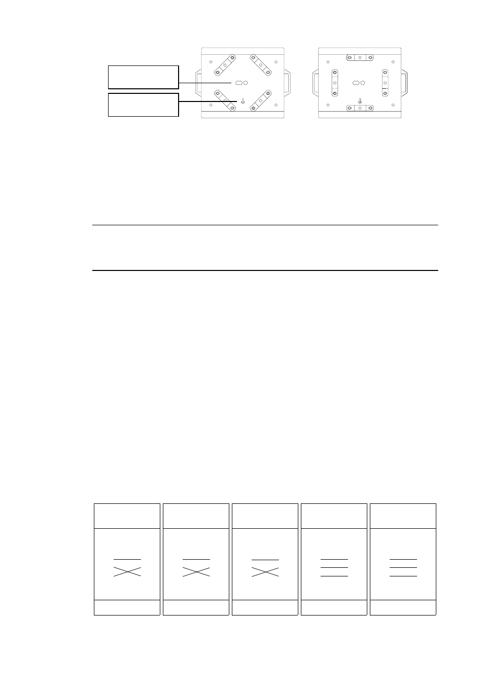
Working from a stable platform, hang the fixture on the truss. The front of the fixture is indicated
by the arrow on the base.
6.
Install a safety wire that can bear at least 10 times the weight of the fixture. The attachment
point is designed to fit a caribiner clamp.
Never use the carrying handles for secondary attach-
ment.
7.
Tighten the rigging clamps securely to the structure.
8.
Verify that there are no combustible materials or surfaces to be illuminated within 1 meter of the
fixture, and that there are no flammable materials nearby.
I M P O R T A N T !
When rigging the fixture within 1 meter of other fixtures, avoid illuminating
one fixture with another. The intense light can melt plastic parts.
C o n n e c t i n g t h e s e r i a l l i n k
T i p s f o r b u i l d i n g a s e r i a l l i n k
1.
Use shielded twisted-pair cable designed for RS-485 devices: standard microphone cable cannot
transmit DMX data reliably over long runs. For links up to 300 meters (1000 ft.) long, you can use 24
AWG, low capacitance, 85-150 ohm characteristic impedance, shielded cable with 1 or more twisted
pairs. For runs up to 500 meters (1640 ft.) use 22 AWG cable. Use an amplifier if the serial link
exceeds 500 meters.
2.
Never use a “Y” connector to split the link. To split the serial link into branches use a splitter
such as the Martin 4-Channel Opto-Isolated RS-485 Splitter/Amplifier.
3.
Do not overload the link. Up to 32 devices may be connected on a serial link.
4.
Terminate the link by installing a termination plug in the output socket of the last fixture on the
link. The termination plug, which is simply a male XLR connector with a 120 ohm, 0.25 watt
resistor soldered between pins 2 and 3, “soaks up” the control signal so it does not reflect back
down the link and cause interference. If a splitter is used, terminate each branch of the link.
C o n n e c t i n g f i x t u r e s
The MAC 500/E has locking 3-pin data input and output sockets that can be configured for use with either DMX or
Martin Protocol controllers.
7KH GHIDXOW SLQRXW LV FRQILJXUHG WR WKH '0; VWDQGDUG, i.e., pin 1 to shield, pin 2
to signal (-) and pin 3 to signal (+).
safety wire
attachment point
arrow points to front
(neutral pan)
Phase-Reversing
Cable
Male
Female
1
2
3
1
2
3
3-pin to 3-pin
Connections
P/N 11820006
Phase-Reversing
Cable
Male
Female
1
2
3
1
2
3
4
5
3-pin to 5-pin
Connections
P/N 11820002
Phase-Reversing
Cable
Male
Female
1
2
3
4
5
1
2
3
5-pin to 3-pin
Connections
P/N 11820003
Straight
Cable
Male
Female
1
2
3
4
5
1
2
3
5-pin to 3-pin
Connections
P/N 11820005
Straight
Cable
Male
Female
1
2
3
1
2
3
4
5
3-pin to 5-pin
Connections
P/N 11820004