Cp-118u block diagram, Dip switch settings, Cp-118u block diagram -2 – Moxa Technologies CP-118U User Manual
Page 10: Dip switch settings -2
CP-118U User’s Manual
Hardware Installation
2-2
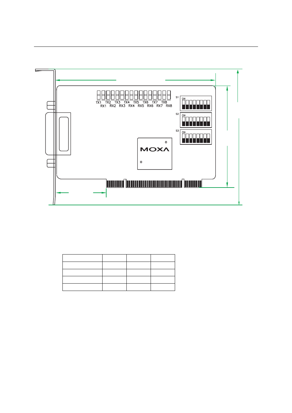
CP-118U Block Diagram
135 mm [5.31 in]
82 mm
[3.23 in]
41.7 mm
[1.64 in]
MU860
CP-1
18U
121 mm
[4.76 in]
DIP Switch Settings
CP-118U has three onboard DIP Switch arrays, each with 8 switches, referred to below and on the
board (see the above block diagram) as S1, S2, and S3. The switches are used to select one of four
serial interfaces—RS-232, RS-422, 4-wire RS-485, 2-wire RS-485—for each of the eight ports.
Note that S3 selects between RS-232 and RS-422/485, S2 selects between RS-422 and RS-485,
and S3 selects between 2-wire and 4-wire RS-485.
Mode S1
S2
S3
RS-232 --- ---
ON
RS-422 ---
ON
OFF
4-Wire RS-485
ON
OFF
OFF
2-Wire RS-485
OFF
OFF
OFF