Product overview, Features, Electrical specifications – Marshall electronic V-R653P-HDSDI User Manual
Page 2: Mechanical specifications, Operational setup, Connectors
• 3 High Resolution 6.5-inch 1.2 MegaPixel wide screens
• 100% digital processing
• High resolution scaling of all images
• Wide viewing radius - 130° horizontal and 120° vertical provides
superior visibility when the viewer is not directly in front of the screen
• 500 candelas per square meter (cd/m2) luminance produces
enhanced image quality in varying light and viewing conditions
• 500:1 ratio of contrast between black and white luminance
values with response rates less than 30 ms results
in excellent quality for moving images
• 4:3 and 16:9 screen aspect ratios for DTV applications in SD formats
• Works with all SMPTE/ITU SDI/HDSDI production formats and frame rates
• Blue Gun for color adjustment
• SD/HD digital signal indicators
• Small Footprint – occupies only 3RU of a standard EIA 19 inch rack
• Ready to mount – all brackets are factory installed
• Lightweight - Save over 30 pounds when compared to similar CRT models
• All adjustments and selections are readily available. No menus!
• Easy to use front panel selection of inputs
• NTSC or Pal operation with automatic signal format detection
• All inputs automatically terminate
• Includes V-PS12-5V-1 Universal power supply (U.L. class 2)
• Unique front mount with tilt adjustment
• Dry erase label for each screen
1
Product Overview
The Rack mounted and tiltable V-R653P-HD represents a technological revolution in LCD imaging for broadcast and profes-
sional video applications. The V-R653P-HD features three state of the art, High Resolution, 1.2 TFT-megapixel™ screens with
completely digital signal processing. All SMPTE/ITU serial digital video standards and signal types are accepted and displayed
on each screen of this model. All video formats are scaled to fi t on screen in the highest resolution using a state of the art LSI
that incorporates 4x4 pixel interpolations with precision Gamma correction to produce the best images available. Each screen
is calibrated to SMPTE standards for Gamma and color temperature.
2
Features
V-PS12-5V-1
Universal power supply
(U.L. class 2)
3 RU
5.14”
13.5 cm
3
Electrical Specifications
Number of Screens
3
Display (Viewing Area)
6.5” Diagonal (16.4cm), (5.67”H x 3.08”V) (144.0mm x 78.24mm)
Viewing Angles
130°H x 120° V
Resolution (Dots)
800H x RGB x 480V (1.2 million pixels)
Dot Pitch
0.06 mm (W) x 0.163mm (H)
Contrast Ratio
500:1
Pixel Response
<30ms
Brightness (in cd/m²)
500 cd/m²
System
NTSC/PAL auto recognition for standard definition signals
Inputs per display
HDSDI/SDI with re-clocked output (BNC)
2
3
V-R653P-
V-R653P-HDSD
HDSDII
Users Guide
Users Guide
Marshall Electronics
Dimensions
19.12”W x 5.14”H x 2.5”D (48.6cm x 130.5cm x 63.5cm)
V-R72P-2HD Weight
6.0 lbs
Power Consumption
12VDC/36 watts. – (5.5 Amps max - UL Class 2 supply included)
4
Mechanical Specifications
5
Operational Setup
1. Unpack the V-R653P-HDSDI and accompanying V-PS12-5V-1 power supply. Physically inspect for any damage that may
have occurred during shipping. Should there be any damage, immediately contact Marshall Electronics at 800-800-6608. If
you are not located within the continental united states call +1 310-333-0606.
2. After inspection, install in your desired location of a standard EIA 19-inch equipment rack. Adequate ventilation is required
when installed to prevent possible damage to the V-R653P-HDSDI internal components.
3. Connect required cables for signal input and output. Please note that power must be applied to the V-R653P-HDSDI for all
outputs to be activated. All BNC connectors should be rated for 75Ω.
4. Plug the V-PS12-5V-1 power supply into the A.C. source
5. Attach twist lock power connection from V-PS12-5V-1 power supply to the back of the unit.
6. Turn on the V-R653P-HDSDI by depressing the power switch located on the front of the unit.
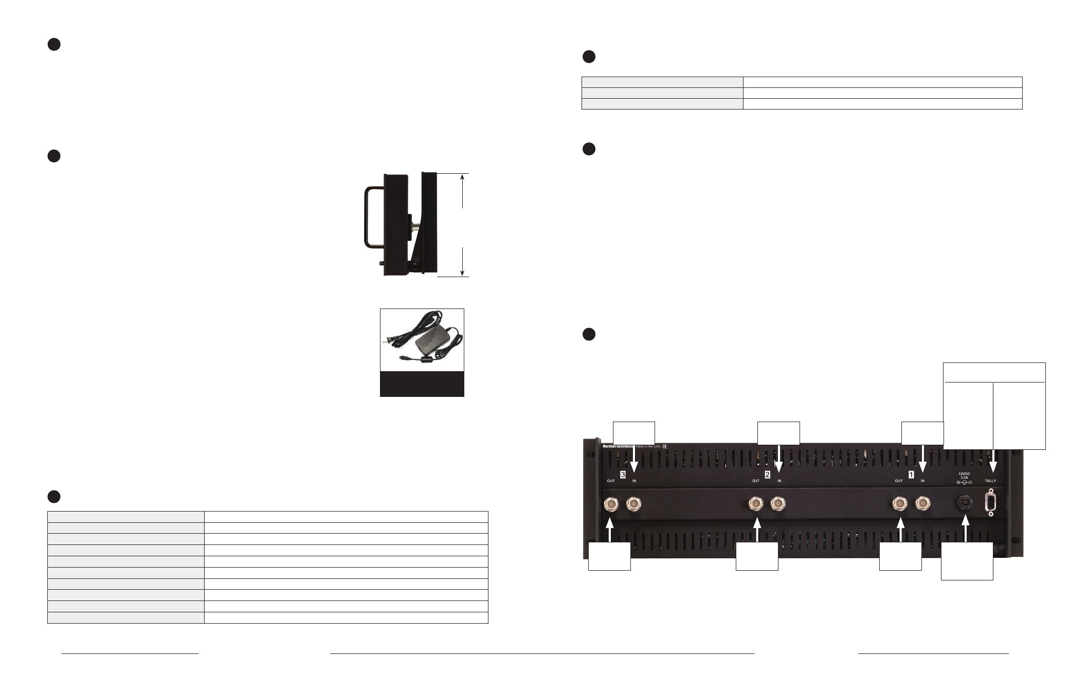
6
Connectors
* HDSDI/SDI inputs comply to SMPTE259M / ITU-R BT601
* All Outputs Require Power to be applied for activation
Monitor 3
HDSDI/SDI
Input
Pin1-M3Grn
Pin2-M3Red
Pin3-M3Yel
Pin4-Gnd
Pin5-Gnd
Pin6-M2Grn
Pin7-M2Red
Pin8-M2Yel
Pin9-Gnd
Pin10-Gnd
Pin11-M1Grn
Pin12-M1Red
Pin13-M1Yel
Pin14-Gnd
Pin15-Gnd
Tally IN
DB-15 Female
12 VDC from
V-PS12-5V-1
power supply
Left Pin - Pos
Right Pin- Neg
Active Output
Re-Clocked
and
Re-Shaped
Monitor 2
HDSDI/SDI
Input
Active Output
Re-Clocked
and
Re-Shaped
Monitor 1
HDSDI/SDI
Input
Active Output
Re-Clocked
and
Re-Shaped