GSW Electric Water Heater P/N 61515 REV. G (05-03) User Manual
Page 2
I) INTRODUCTION
Thank you for purchasing this water heater. Properly installed and
maintained, it will provide years of trouble free service.
The warranty on this water heater is in effect only when the water heater
is installed and operated in accordance with these instructions. The man-
ufacturer of this water heater will not be liable for any injury or property
damage resulting from failure to comply with these instructions.
WARNING!
This water heater must be installed strictly in accordance
with the instructions enclosed, and local electrical, fuel and building
codes. It is possible that connections to the water heater, or the water
heater itself may develop leaks. IT IS THEREFORE IMPERATIVE that
the water heater be installed so that any leakage of the tank or related
water piping is directed to an adequate drain in such a way that it cannot
damage the building, furniture, carpeting, adjacent areas, lower floors of
the structure or other property subject to water damage. This is particu-
larly important if the water heater is installed in a multi-story building, on
finished flooring or carpeted surfaces. GSW CANNOT BE HELD
LIABLE for damage caused by water from the water heater, pressure
relief valve, or related fittings where adequate provision to drain such
water has not been made. Closets without drains and carpeted areas are
examples of unsuitable locations for any water heater. Select a location as
centralized within the piping system as possible. The heater should be
located in an area not subject to freezing temperatures. In any location
selected it is recommended that a suitable drain pan be installed under the
water heater. This pan shall be an minimum of 50mm (2 in.) deep and
have a diameter that is a minimum of 50mm (2 in.) greater than the diam-
eter of the water heater. Suitable piping shall connect the drain pan to a
properly operating floor drain. If this heater is to be installed directly on
carpeting, the carpeting must be protected by a metal or wood panel
beneath the heater, extending beyond the full width and depth of the
heater by a minimum 80mm (3 in.). If the heater is installed in a closet or
alcove, the entire floor must be covered by the panel. This panel must be
strong enough to support the weight of the heater full of water without
breaking. Failure to heed this warning may result in a fire hazard. When
used with a fuel-fired heater, this drain pan must not restrict combustion
air flow.
Caution:
Hydrogen gas can be produced in a hot water system served
by this heater that has not been used for a long period of time (generally
two (2) weeks or more).
Hydrogen gas is extremely flammable and can
ignite when exposed to a spark or flame. To reduce the risk of injury
under these conditions, it is recommended that the hot water faucet be
opened for several minutes at the kitchen sink before using any electrical
appliance connected to the hot water system. Use caution in opening
faucets. When hydrogen is present, there will probably be an unusual
sound such as air escaping through the pipe as the water begins to flow.
There should be no smoking or open flame near the faucet at the time it
is open.
II) SAFETY
Relief Valve Requirements
Caution:
To reduce the risk of excessive pressures and temperatures in
this water heater, install temperature and pressure protective equipment
required by local codes. It should be no less than a combination temper-
ature and pressure relief valve certified by a nationally recognized testing
laboratory that maintains periodic inspection of production of listed
equipment or materials, as meeting the latest edition of
ANSI
Z21.22/CSA 4.4 Requirements for Relief Valves for Hot Water
Supply Systems. This valve must be marked with a maximum set pres-
sure not to exceed the marked MAXIMUM working pressure of the water
heater (150 PSI). Install the valve into an opening provided and marked
for this purpose in the water heater, and orient it or provide tubing so that
any discharge from the valve will exit only within 6 inches above, or at
any distance below the structural floor and cannot contact any live elec-
trical part. The discharge opening must not be blocked or reduced in size
under any circumstances. The end of the relief pipe opening should ter-
minate near a floor drain or other suitable location not subject to block-
ing or freezing. DO NOT thread, plug or cap the relief pipe opening.
III) INSTALLATION
Plumbing
1. The cold water inlet is identified at the top of the heater (unless bot-
tom entry). The hot water connection is also identified at the top of
the heater. Install a shut-off valve in the cold line approximately 3'
from the inlet to the heater where it is in convenient reach. This valve
is for emergency shut-off and MUST be kept open during the opera-
tion of the heater.
2. The water connection fittings contain a plastic lining to minimize cor-
rosion and some models include plastic heat traps. Do not apply heat
to these nipples when making solder connections. Sweat a piece of
tubing to adapter before fitting adapter to nipple.
3. After installing the water piping, cover with the pipe insulation (if sup-
plied with this heater). Use the insulation to cover 2' of hot and cold
piping nearest to the heater.
4. A combination Temperature and Pressure relief valve MUST be
installed. In some cases it is necessary that a Tee be fitted in the top
of the heater which allows the temperature probe to reach into the top
of the tank. See diagram on page 4. No shut-off valve of any kind is
permitted between the tank and the relief valve. The outlet of the
relief valve must be piped to a drain or fixture, and must terminate
within 6" of the floor.
Electrical
1. Check to see that the element marking and nameplate data do corre-
spond with the electric service available.
a)
The junction box where electrical connections are made is
located near the top of the heater, near the upper access door.
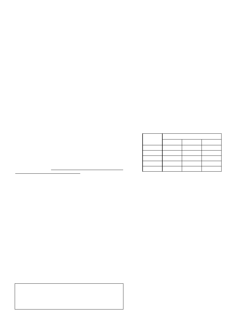
2. Install a circuit directly from the main fuse box. This circuit must be
the right size for the length of run and the load (see chart below).
3. A ground wire must run from the green ground screw provided at the
electrical connection point in the heater junction box to the ground
connection at the service panel.
4. Adequate fusing must be provided at the service entrance as required
by local codes and/or electric utility having jurisdiction. This can be
accomplished with either a circuit breaker or fuse block in the service
panel or a separate disconnect switch, so that electric power can be
shut off easily when working on the heater.
5. Final connections are made at the junction box in the heater. Access
to the junction box is obtained by removing the cover near the knock-
outs.
6. The heater you have received is internally wired. A specific wiring
diagram is located inside the upper door or for certain models on the
rating plate. All wiring is colour-coded and connections must be made
as shown in the wiring diagram.
MAKE SURE HEATER IS COMPLETELY FILLED WITH
WATER BEFORE POWER IS TURNED ON. SEE 'FILLING
TANK' SECTION.
Wiring
TWO WIRE CIRCUIT FOR NON-SIMULTANEOUS OPERATION.
SINGLE HIGH LIMIT.
The basic operation of a two thermostat system (upper and lower) on an
electric water heater of 240 volts is as follows:
Only one element will come on at any one time. This is known as a
flip/flop system. On a 240-volt water heater, there will always be 120
volts to both elements. The thermostat will direct the second leg of the
120-volt to the element to complete the 240 volts required for energizing
the element.
Initial Start Up: When the tank is full of cold water, the upper thermo-
stat will take priority and the top portion of the water will heat up to the
setting of the thermostat. Once that temperature has been reached, the
thermostat will then flip down the 120 volts to the lower thermostat. The
thermostat switch closes and the bottom portion of the tank heats up until
the water reaches the setting on that thermostat. At this point the tank will
be full of hot water.
2
FAILURE TO INSTALL A LISTED 3/4” TEMPERATURE -
PRESSURE RELIEF
VALVE WILL
RELEASE THE
MANUFACTURER FROM ANY CLAIM WHICH MIGHT
RESULT FROM EXCESSIVE TEMPERATURES AND PRES-
SURES.
The heater must be well grounded.
RECOMMENDED FOR AMPERAGE
MAX.
WATTS
120 V
208 V
240 V
1500
20 A
10 A
10 A
3000
35 A
20 A
20 A
3500
40 A
20 A
20 A
4500
30 A
25 A
5500
35 A
35 A
MAX. VOLTS