Performance data em-40, Specifications, Em-10 – Greenheck Fan Extruded Backdraft Damper EM-40 User Manual
Page 2: Pressure drop, Pressure limitations velocity limitations, Leakage, 201 kg/m, Æp in. wg (pa), Operational data
Specifications
Backdraft dampers meeting the following specifications shall
be furnished and installed where shown on plans and/or as
described in schedules. Dampers shall consist of: heavy gauge
6063T5 extruded aluminum channel frame (0.125 in.[3.2mm]
thick) with 3
1
Ú
8
in. (79mm) depth; blades from 0.070 in.(1.8mm)
6063T5 extruded aluminum;
3
/
4
in. (19mm) dia. metallic axles
turning in acetal bearings; damper shall be equipped with
extruded vinyl blade seals; and internal
1
/
8
in. (3mm) plated
steel blade-to-blade linkage. Damper manufacturer’s printed
application and performance data including pressure, velocity
and temperature limitations shall be submitted for approval
showing damper suitable for pressures to 10 in. wg (2491 Pa),
velocities to 3500 fpm (18 m/s) and temperatures to 180°F
(82ºC). Testing and ratings to be in accordance with AMCA
Standard 500-D. Basis of design is Greenheck model EM-40.
Velocity (fpm)
1
x 10
Pr
essur
e Loss (
In.
w
g
)
10
9
8
7
6
5
4
3
2
2 3 4 5 6 7 8 9 10
1.0
.9
.8
.7
.6
.5
.4
.3
.2
.10
.09
.08
.07
.06
.05
.04
.03
.02
x 100
2 3 4 5 6 7 8 9 10
x 1000
2 3 4 5 6 7 8 9 10
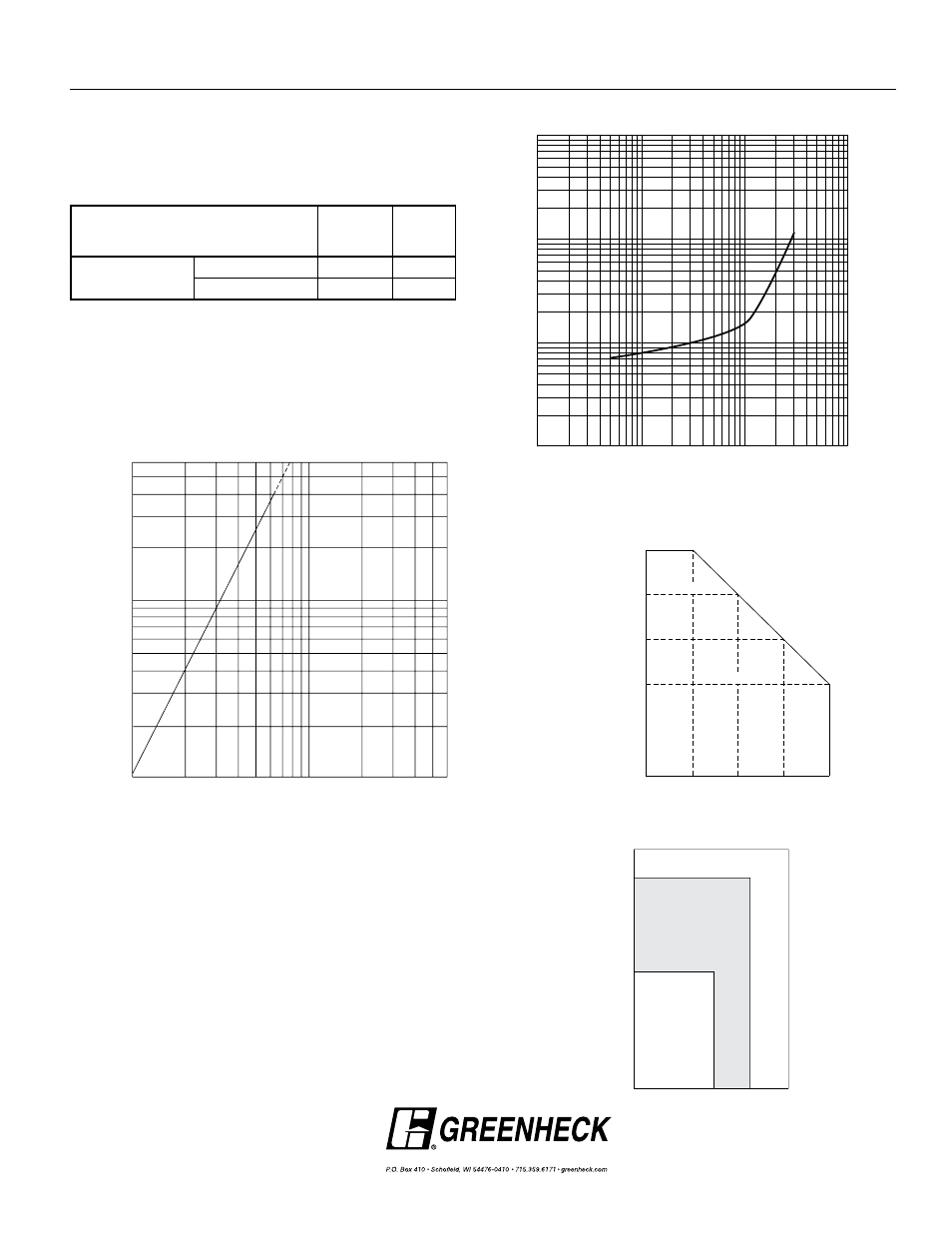
Pressure Drop
Performance data results from testing a 36 in. x 36 in.
(914mm x 914mm) damper in accordance with AMCA Standard
500-D using Figure 5.7A (unducted). All data has been corrected
to represent standard air at 0.075 lb/ft
3
(1.201 kg/m
3
).
Pressure Limitations
Velocity Limitations
Pr
essur
e (in. w
.g.)
48
36
24
12
0
8
6
4
2
0
4.0 in. w.g.
6.0 in. w.g.
Damper Width (in.)
10
8.0 in. w.g.
10.0 in. w.g.
0
12
24
36
48
0
60
74
3000 fpm
2500 fpm
Damper Height (in.)
Damper Width (in.)
3500 fpm
36
140
1.0
.9
.8
.7
.6
.5
.4
.3
.2
6
5
4
3
2
Static Pr
essur
e Dif
fer
ence
Air Leakage in CFM/Sq. Ft.
1 2 3 4 5 6 7 8 9 1 0
20 30 40 50 60
Static Pr
essu
re
Di
ff
er
ence
1.0
.9
.8
.7
.6
.5
.4
.3
.2
10
9
8
7
6
5
4
3
2
Air Leakage in CFM/Sq. Ft.
1 2 3 4 5 6 7 8 9 10
20 30 40
50 60 70 80 90 100 150
EM-10
Air Leakage in CFM/Sq. Ft.
1 2 3 4 5 6 7 8 9
10
20 30 40
50 60 70 80 90 100 150
1.0
.9
.8
.7
.6
.5
.4
.3
.2
8.5
8
7
6
5
4
3
2
Static Pr
essur
e Dif
fer
ence
130
Wit
h
S
eal
s
W
ith
ou
t S
ea
ls
Leakage testing was conducted in accordance with AMCA
Standard 500-D and is expressed as CFM per sq. ft. of damper
face area. All data has been corrected to represent standard air
at 0.075 lb/ft
3
(1.201 kg/m
3
).
Leakage
36 in. x 36 in. Damper
Copyright © 2008 Greenheck Fan Corporation
EM-40 Rev 4 Aug 2008
Performance Data EM-40
Operational Data
ÆP in. wg
(Pa)
Veloc-
ity fpm
(m/s)
Damper with Standard
Bearings
Blades Start to Open
0.07 (17)
50 (.254)
Blades Fully Open
0.20 (50)
1200 (6.2)