GE Profile JSP46DPBB User Manual
Jsp46dp, 30" slide-in cleandesign electric range, Dimensions and installation information
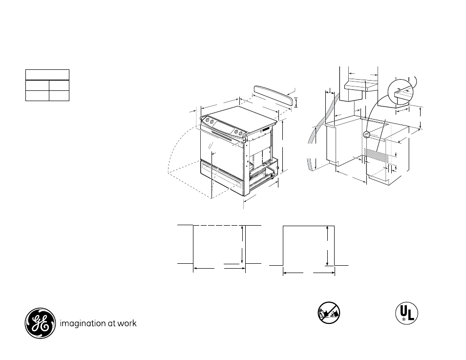
Dimension and installation information are shown in inches.
JSP46DP
GE
®
30" Slide-In CleanDesign Electric Range
Dimensions and Installation Information
Specification Created 5/09
320649
For answers to your Monogram,
®
GE Profile
™
or
GE
®
appliance questions, visit our website at
ge.com or call GE Answer Center
®
service,
800.626.2000.
All GE ranges are equipped with
an Anti-Tip device. The installation
of this device is an important,
required step in the installation
of the range.
Optional Kits For Slide-In
Electric Ranges
(Available at additional cost)
Lower/Side Trim Kits Accessory
Backguards
JXS56 - Lower Trim Kit
JXS37 - Backguard
JXS86 - Vertical Side Trim Kit
JXS77 - Body Sides
Rear Filler Strip
WB07T10680 - Black Filler Strip Assembly
WB07T10681 - White Filler Strip Assembly
Note: To reduce possiblity of scorching of the side wall
adjacent to the heating elements, it is recommended
a minimum of 6” spacing from adjacent side walls
be allowed for possible extended, high-heat, no-load
operation of heating elements.
Receptacle Location: For all 30” Slide-In Ranges locally
approved flexible service cord or conduit must be
used because terminals are not accessible after range
installation. See shaded area in drawing for location of
electrical outlet box. Recommended outlet locations
allow range to be installed directly against rear wall.
Note: Cabinets installed adjacent to slide-in ranges
must have an adhesion spec of at least 194°.
Installation Information: Before installing, consult
installation instructions packed with product for
current dimensional data.
KW Rating
240V
12.4
208V
9.3
If you are NOT using the
optional Filler or Backguard:
23-3/16
30
If you are using the optional
Filler or Backguard:
25
30
Listed by
Underwriters
Laboratories
Acceptable
Electrical
Outlet Area
30" Min.
30" Min.
Shave Raised Edge To Clear
31-1/8" Wide Control Panel
Excluding Models JSS28 and JSP39
2-7/8"
To Front
Surface Of
Countertop
20-5/8" Door
Clearance
From Front
Surface of
Countertop
31-1/4
30
25-3/4**
Recommended
6" Min.
From Walls
23-3/16
15" Min.
A/B*
13" Max.
2-1/2
30
25
9/16
7-1/2
2-1/2
Accessory
Backguard
24
36-1/4
*JXS37 is 5-1/4" and JXS32 is 4"
(excluding handle)
**Total depth from wall to
front of closed oven door
including handle is 27-13/16.
35-7/8"–38"
from floor to
countertop
If the countertop area is not flat, excess tension may be applied to the glass cooktop causing breakage
and voiding the warranty. Make sure the wall covering, countertop, flooring and cabinets around the range
can withstand the heat (up to 200˚F) generated by the range.
A. Allow 30" minimum clearance between surface units and bottom of unprotected wood or metal cabinet,
or allow a 24" minimum when bottom of wood or metal cabinet is protected by no less then 1/4" thick
flame retardant millboard covered with no less than No. 28 MSG sheet metal (.015" thick), .015" thick
stainless steel, .025" aluminum or .020" copper.
B. This appliance has been approved for 0" spacing to adjacent surfaces above the cooktop. However,
a minimum 6" spacing to surfaces less than 15" above the cooktop and adjacent cabinetry
is recommended to reduce exposure to steam, grease splatter and heat. Allow 1/4" minimum clearance
at the back wall.
To reduce the risk of burns or fire when reaching over hot surface elements, cabinet storage space above
the cooktop should be avoided. If cabinet storage space is to be provided above the cooktop, the risk can
be reduced by installing a range hood that projects at least 5" beyond the front of the cabinets. Cabinets
installed above the cooktop must be no deeper than 13".