Table 1, Figure 3 — led indicators on front panel, Jumper position* description – Generac Power Systems Digital Controller R-200A User Manual
Page 5: General information, R-panel technical manual
3
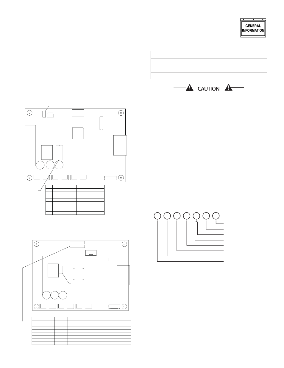
Jumper JMP1/S2: Selects the engine displacement.
Set to position 1 and 2 for 1.6L. Set to position 2
and 3 for 2.4L. The jumper is not used on PCB's
0G1505A or 0G1505B. On later revisions, JMP1 is
replaced by S2. S2 has no effect on 4.2L operation
and is ignored when DIP Switch Position 7 is ON.
Figure 1 — Dip Switch & Jumper Settings
(Old Revision)
RL1
U9
J2
J3
J5
J4
U7
J1
2
3
4
5
7
8
6
1
ON
DATE XXXX
SOFTWARE P/N
REV #
DIP SWITCH
LOW SPD
8
5
6
7
4
3
LP
1.6L
NORMAL
NG
POS
1
2
OFF
ATS
GTS
ON
RESERVED
RESERVED
FUEL TYPE
ENGINE TYPE
EXERCISE MODE
RESERVED
TRANSFER SWITCH MODE
DESCRIPTION
2.4L
kW RATING FOR 2.4L, 3600rpm
45kW
35kW
1
3
JUMPER - JMP1
Figure 2 — Dip Switch & Jumper Settings
(New Revision)
2.4
1.6
S2
ON
8 7 6 5 4 3 2 1
DIP
SWITCH
U6
S1
J5
J3
J1
J2
C13
C14
C15
RL1
S2
U12
POS
OFF
ON
DESCRIPTION
1
2
3
4
5
6
7
8
LP
2.4L
45kW
ATS
LOW SPD
GTS
NORMAL
1.6L
35kW
NG
RESERVED
kW RATING FOR 2.4L 3600 RPM AND 4.2L, 1800 RPM
ENGINE TYPE WHEN POS 7 IS OFF
EXERCISE MODE
FUEL TYPE
ENGINE SELECT FOR 4.2L
RESERVED
TRANSFER SW. MODE
1.6L, 2.4L
4.2L
Jumper Position*
Description
1 & 2
1.6L Selected
2 & 3
2.4L Selected
* When S2 is used, see decal adjacent to S2. Ignored when Pos 7 is ON.
If the DIP switch and jumper settings are not set
correctly, the generator engine may run rough,
not start or not provide rated power. When LP
fuel is used it is very important that DIP Switch
Position 4 be in the LP fuel position (switch
OFF).
LED Indicators visible through front panel (see Table
1 and Figure 3).
Table 1
System Ready
Green LED
Low Fuel Pressure
Yellow LED
Low Battery
Red LED
Low Oil Pressure
Red LED
Hi Coolant Temp/Low Coolant Level
Red LED
Over Speed/RPM Sensor Loss
Red LED
Over Crank
Red LED
Figure 3 — LED Indicators on Front Panel
OVERCRANK
OVERSPEED
LOW COOLANT LEVEL
HI COOLANT TEMPERATURE
LOW OIL PRESSURE
LOW BATTERY
LOW FUEL PRESSURE
SYSTEM READY
•
•
•
•
•
•
•
General Information
R-panel Technical Manual