Engineered transfer switch (2-wire start gts mode) – Generac Power Systems Digital Controller R-200A User Manual
Page 11
9
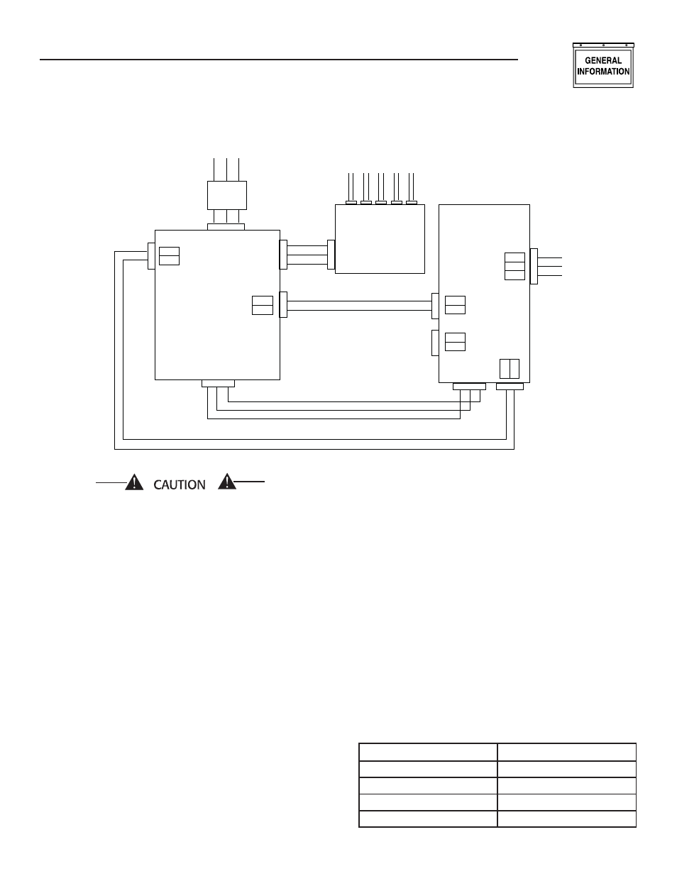
Be very careful when connecting high-voltage
wires labeled N1 and N2 and low-voltage wires
labeled 23 and 194 in both the generator wiring
panel and the transfer switch wiring panel. The
control board will be damaged if these wires are
not connected correctly.
In order for the generator battery charger function
to work, it is necessary to provide a 120VAC util-
ity source connection to the generator wiring panel
LINE, NEUTRAL and GND terminals (see Figure 4).
ENGINEERED TRANSFER SWITCH
(2-WIRE START GTS MODE)
When required, the generator can be installed with
an engineered W-type transfer switch which controls
utility voltage sensing, weekly exercising and load
transferring.
When Position 2 of the eight-position DIP switch,
which is located on the generator circuit board (see
Figures 1 and 2), is in the ON position then utility
voltage sensing, weekly exercising and load transfer-
ring is under the control of the engineered W-type
transfer switch (GTS Mode).
Generator control board DIP switch position 2 ON =
2-wire Start GTS Mode:
The generator control board will NOT monitor the
utility.
The generator control board will NOT perform a
weekly exercise. (In GTS mode the green system
ready LED will be ON for five (5) seconds and OFF
for one (1) second).
The generator control board will NOT activate the
transfer output.
The generator control board WILL monitor all
engine conditions and shut down on all the faults
listed in this document.
For the W-type transfer switch to control utility volt-
age sensing, weekly exercising and load transferring,
suitable wiring must also be connected from the
transfer switch 178 and 183, 2-wire start terminals
to the corresponding generator 178 and 183 2-wire
start terminals. Recommended wire gauge sizes for
the 2-wire start wiring depend on the length of the
wire (see wiring length chart).
MAXIMUM WIRE LENGTH
RECOMMENDED WIRE SIZE
460 feet (140M)
No. 18 AWG.
461 TO 730 feet (223M)
No 16 AWG.
731 to 1,160 feet (354m)
No 14 AWG.
1,161 to 1,850 feet (565m)
No 12 AWG.
•
•
•
•
General Information
R-panel Technical Manual
FROM UTILITY
TO LOAD
FEEDER CIRCUITS
LOAD
DISTRIBUTION
PANEL
GENERATOR
194
23
178
183
N2 N1
E1 E2 (E3)
194
23
N1 N2 (N3)
N1
N2
FUSE
FUSE
RTS-TYPE
OR
HS-TYPE
TRANSFER
SWITCH
T1
T2
(T3)
MAIN LINE
CIRCUIT
BREAKER
OR FUSE
LINE
NEU
GND
CHARGER
120 VAC
E1 E2 (E3)
Figure 4 - Connection Diagram (ATS Mode)