Wire guide, Fig. 3-4 mounting wall control, Fig. 3-3 insert wires – Genie 2024 User Manual
Page 16: Power head with rear cover removed), Fig. 3-5 mounting entrapment warning label, Insulated staple, Independent light control, Controls door opener lights from inside garage, Door control "open/close" button, Open and closes door from inside garage
PN# 37026500123 05/15/2009
16
3. Securely fasten wires.
• Securely fasten wires to ceiling and
wall using insulated staples provided.
– Use insulated staples.
– Staples should be snug only.
• If rear cover is attached to power head,
remove it.
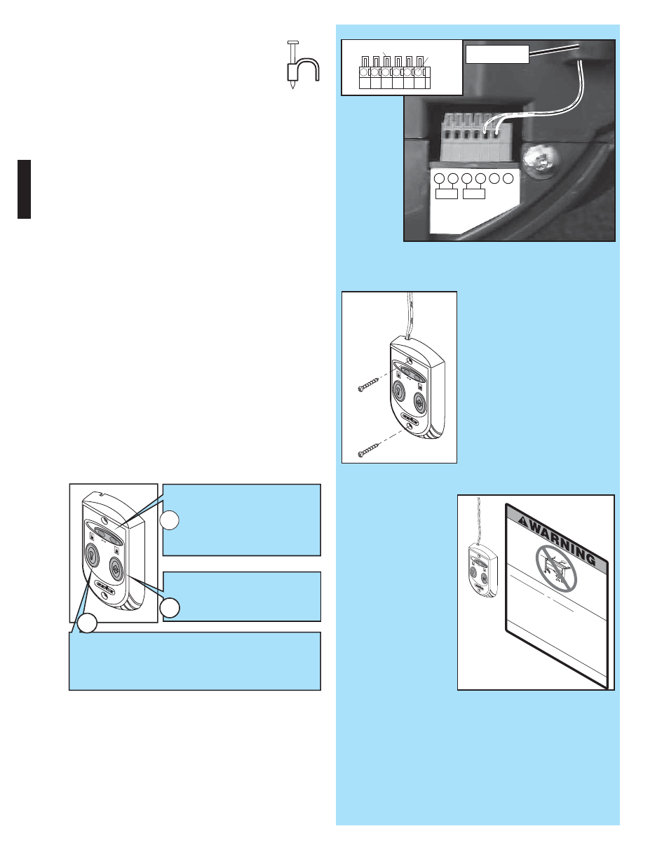
• On power head:
– Route Wall Control wires through wire guide
on power head.
– Split and strip ends of wire
(Fig. 3-2 on
previous page).
– Insert wire into terminal holes and lightly press in
the orange locking clips above each terminal
hole. (You can use a pencil or small screwdriver
to comfortably press in locking clips.) The white
wire into #1 terminal hole and striped wire into
the #2 terminal hole.
– Confirm wire lock by lightly tugging on the wire.
The wire should remain in the terminal hole.
•
Do NOT install rear cover yet.
4. Mounting.
• Fasten Wall Control to wall with 2 screws
(provided)
(Fig. 3-4).
• Remove protective backing from "Entrapment"
warning label
(Fig. 3-5). The "Entrapment" label
is located in the center of this manual.
– Stick label on wall near Wall Control.
FIG. 3-4 Mounting Wall Control.
Chil
d ca
n be
pin
ned
und
er
autom
atic
gara
ge
doo
r.
Dea
th
or
ser
ious in
jury
can
res
ult.
•
Nev
er let
child w
alk
or ru
n un
de
r m
oving
door
.
.
•
Nev
er let
child
use
doo
r op
en
er co
ntrols
.
•
Alw
ays
kee
p m
ovin
g d
oor
in sight.
•
If p
erson
is p
inne
d, pu
sh
contro
l bu
tto
n o
r use
em
erge
ncy
rele
ase
.
•
Test doo
r ope
ner
mon
thly:
Refer
to y
our o
wner
'
’
s m
anua
l.
Pla
ce 1
1
/
2
-inch
objec
t (or
2x4
laid
flat)
on
floo
r.
If
do
or fa
ils to
reve
rse
on c
onta
ct,
ad
just
ope
ne
r.
If op
ener
still f
ails
to
revers
e do
or, repa
ir o
r rep
lace
ope
ner
.
Do n
ot
remove
or p
aint
ove
r th
is la
be
l.
Mou
nt wall
control
out
of chi
ld's
reach
(at lea
st
5 fe
et abov
e floor)
.
Plac
e next
to
wal
l con
trol.
©199
9
Insulated
Staple
+ –
P
B
Infared Sensor
1
2
3
4
5
6
FIG. 3-3 Insert wires
.
(Power Head With Rear Cover Removed)
1
2
3
4
Terminal
Holes
Locking
Clips
5
6
FIG. 3-5 Mounting Entrapment warning label.
3
2
1
Independent Light Control
–
Controls door opener lights from inside garage
–
Energy-Saver shut-off turns OFF lights 3 minutes after
door activation
Vacation Locking Switch
– LOCK disables controls after
door is completely closed
– UNLOCK allows controls to
work normally
Door Control "Open/Close" Button
–
Open and closes door from
inside garage
wire guide