15 Page 34
Page 34
3307568 User’s Manual Hardware Setup
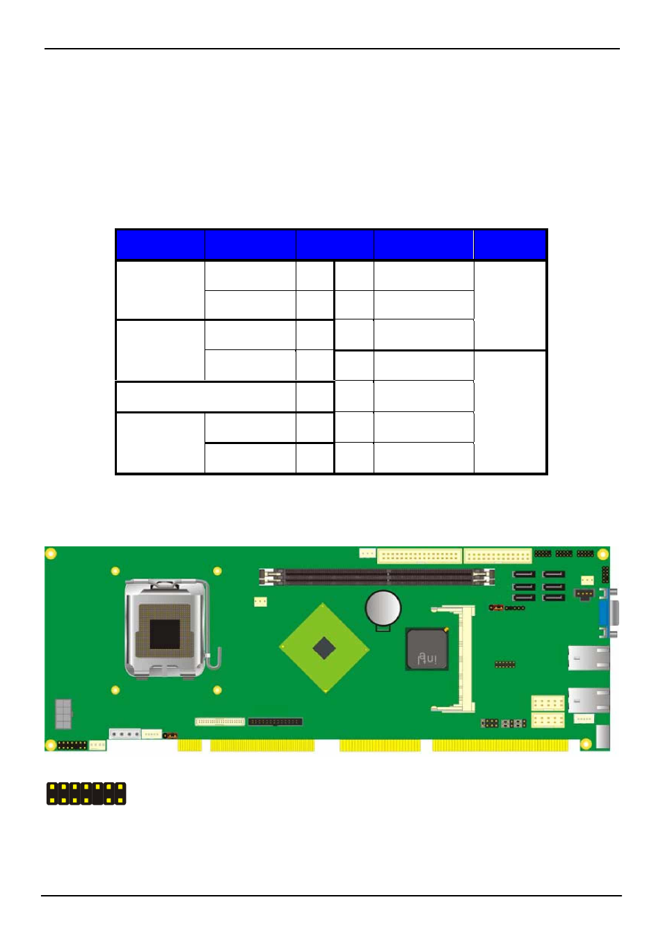
2.15
The JFRNT provides front control panel of the board, such as power button, reset and
beeper, etc. Please check well before you connecting the cables on the chassis.
Connector: JFRNT
Type: onboard 14-pin (2 x 7) 2.54-pitch header
Function
Signal
PIN
Signal
Function
IDE LED
Reset
HDLED+
1
2
PWDLED+
HDLED-
3
4
N/C
Reset+
5
6
PWDLED-
Reset-
7
8
SPKIN+
Power
LED
N/C
9
10
N/C
Power
PWRBT+
11
12
N/C
Speaker
Button
PWRBT-
13
14
SPKIN-
JFRNT
2
14
1
13
34
Switch and Indicator