Connections, Configuration, Ge multilin – GE F485 User Manual
Page 4: F485 communications converter
F485 COMMUNICATIONS CONVERTER
Page
4 of 8
g
GE Multilin
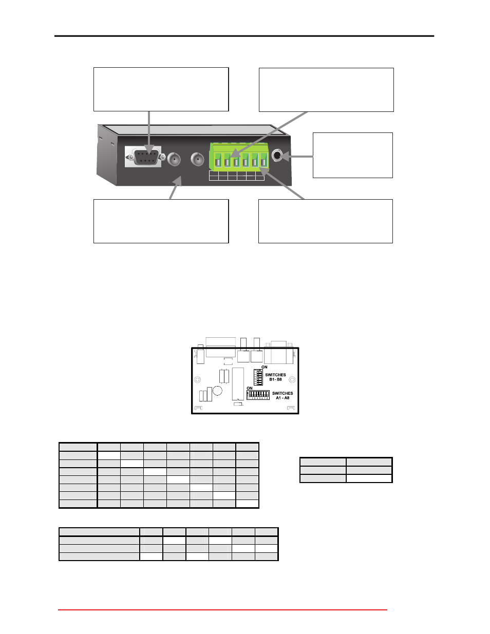
CONNECTIONS
805700A1.CDR
RS232
COMPUTER
FIBER OPTIC
RS485
POWER
POWER
9V
AC/DC
Tx
Rx
COM
RS232
FIBER
POWER JACK
The RS232 connector on the F485 converter accepts a
standard 9-pin computer cable. See wiring diagram for pin
assignments.
The fiber input/output will accept 50/125, 62.5/125 and
100/140um fiber sizes using ST terminated cables. Care
should be taken when removing the protective caps to
prevent dust from entering the connectors.
Connect the supplied power
adapter to this input if power is not
supplied via the terminals. The
power adapter steps down
120/220 VAC to 9 VAC.
RS485
The RS485 terminals accept a standard shielded twisted
pair (such as Beldon 9841) and provide connections for a
"+", "-" and a shield. The RS485 terminals have a
terminating network installed internally and therefore, no
external terminating network is required. Observe correct
polarity.
POWER TERMINALS
The power terminals accept either 9 VAC or 9 VDC to power
the F485 converter instead of using the power adapter. The
GND terminal must be connected to ground to ensure
adaquate protection against transients. Pin 4 is the main
transient ground for the converter.
GND
1
2
3
4
5
6
+
-
+
-
Figure 3: Connections
CONFIGURATION
The converter box is configured via two internal dip switch banks which are accessible by removing the
converter box cover. Switches A1-A8 are used to set the baud rate for RS485 communications and
determine whether the converter is DTE (RS232 direct) or DCE (RS232 modem). Switches B1-B6 are
used to select the interface type. The designator for each switch is clearly marked on the printed circuit
board. The tables shown below provide a description of each switch within the switch banks.
Figure 4: Switch Locator
SWITCH A (BAUD RATES)
BAUD
A1
A2
A3
A4
A5
A6
A7
1200
ON
OFF
OFF
OFF
OFF
OFF
OFF
2400
OFF
ON
OFF
OFF
OFF
OFF
OFF
4800
OFF
OFF
ON
OFF
OFF
OFF
OFF
9600
OFF
OFF
OFF
ON
OFF
OFF
OFF
19200
OFF
OFF
OFF
OFF
ON
OFF
OFF
38400
OFF
OFF
OFF
OFF
OFF
ON
OFF
57600
OFF
OFF
OFF
OFF
OFF
OFF
ON
SWITCH B (CONFIGURATION)
CONFIGURATION
B1
B2
B3
B4
B5
B6
RS232 TO RS485
OFF
ON
OFF
ON
OFF
OFF
RS232 TO FIBER
OFF
OFF
OFF
OFF
ON ON
RS485 TO FIBER
ON
OFF
ON
OFF
OFF
OFF
SWITCH A (DTE/DCE)
MODE
A8
DTE
OFF
DCE
ON