Product selection guide, R2 t 0 s n 0 g 3, Generac - life is better with power – Generac Power Systems Transfer Switches and Accessories User Manual
Page 13
Generac - life iS better witH Power.
14
Product Selection Guide
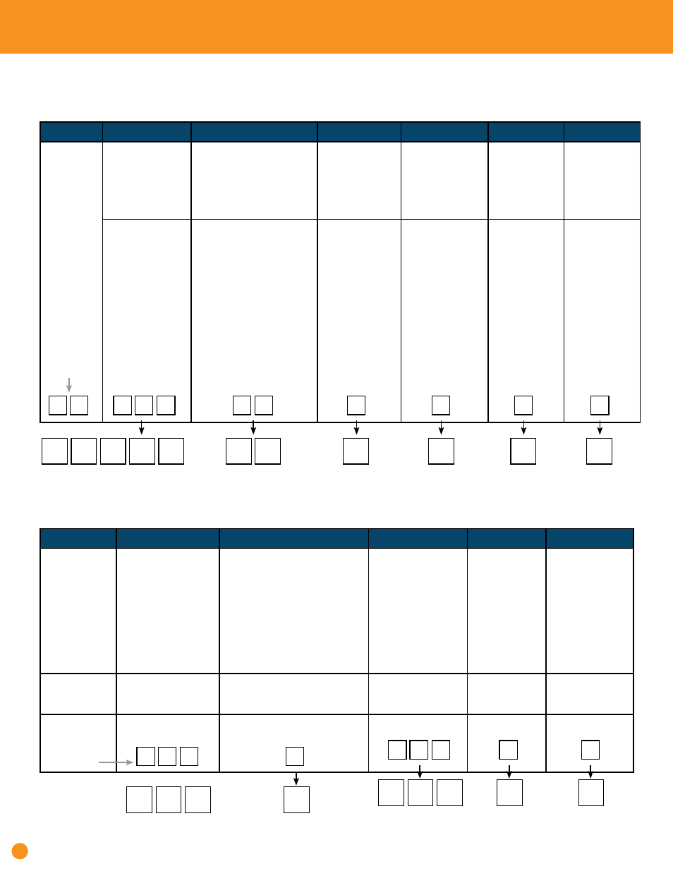
LIQUID-COOLED GENErATOrS
TrANSfEr SWITCHES
to build a generator and transfer switch, specify each ordering option below.
Generator voltage ratings must match transfer switch voltage.
STEP 1
STEP 2
STEP 3
STEP 4
STEP 5
STEP 6
ALL
MODELS
bEGin
WiTH QT
kW Ratings
e.g. (45 kW = 045)
Engine
e.g. (5.4L = 54)
Voltage
120/240 1ø = A
120/208 3ø = G
120/240 3ø = J
277/480 3ø = K
Fuel
Natural Gas = n
Propane Vapor = V
Field Convertable
to LP = *
Enclosure
Steel = S
Aluminum = A
Emission/
Catalytic
Converter
No Catalyst = n
1
Catalyst & A/F
Ratio = Y
22
25
27
30
36
45
48
60
60
70
80
100
130
150
2.4L @ 1800 RPM
1.6L @ 3600 RPM
2.4L @ 1800 RPM
1.6L @ 3600 RPM
2.4L @ 1800 RPM
2.4L @ 3600 RPM
4.2L @ 1800 RPM
2.4L @ 3600 RPM
2.4L @ 3600 RPM
6.8L @ 3600 RPM
4.6L @ 3600 RPM
6.8L @ 2300 RPM Gear Drive
6.8L @ 3000 RPM Gear Drive
6.8L @ 3600 RPM
A,G,J
A,G,J
A,G,J
A,G,J
A, G, J, K
A, G, J, K
A, G, J, K
A, G, J, K
A, G, J, K
A, G, J, K
A, G, J, K
A, G, J, K
A, G, J, K
A, G, J, K
n*
n*
n*
n*
n*
n*
n*
n
V
n, V
n, V
n, V
n, V
n, V
A
S
A
S
A
S
A
S
S
S, A
S, A
S, A
S, A
S, A
n/A
n/A
n/A
n/A
n/A
n, Y
n, Y
n
n
n
n
n, Y
n, Y
n, Y
Q
Q T
0
T
6
2
0
4
K
N
S
N
1 = Catalyst & A/F Ratio may not be available for all models. Contact Your Generac representative for more information.
MODEL nuMbER
(Enter on Order Form)
SAMPLE
STEP 1
STEP 2
STEP 3
STEP 4
STEP 5
Selection Criteria
Transfer Switch
R Controller = RTS
H-100 Controller = HTS
Load Shedding
2
= S
Switch Type
Normal = n
Service Entrance Rated
1
= E
8 cct. Integrated Load Center
2
= D
10 cct. Integrated Load Center
2
= F
12 cct. Integrated Load Center
2
= H
14 cct. Integrated Load Center
2
= P
16 cct. Integrated Load Center
2
= W
16 cct. Priority Load Center,
Load Shedding
3
= S
Amp Rating
e.g. (200 Amp = 200)
Voltage
120/240 1ø = A
120/208 3ø = G
120/240 3ø = J
277/480 3ø = K
Enclosure Type
3,4
NEMA 1 = 1
NEMA 3R = 3
NEMA 12 = 4
For Standby
Generators
8 - 60 kW
RTS
n, E, D, F, H, P, W, S
100, 200, 400
A, G, J, K
1, 3
For Standby
Generators
70 - 150 kW
HTS
n
100, 150, 200,
400, 600, 800
A, G, J, K
1, 3, 4
R
2
T
0
S
N
0
G
3
1 = 120/240 1ø, NEMA 3R Only 2 = 200 Amp service entrance rated NEMA 3R 3 = HTS 100 - 400 Amp NEMA 1/3R Only 4 = HTS 600 - 800 Amp NEMA 12/3R Only
PRODuCT nuMbER
(Enter on Order Form)
SAMPLE