Introduction, Features, Cautions – Gemini PMX-500 User Manual
Page 3: Connections, Operation, Specifications
( 3 )
INTRODUCTION:
Congratulations on purchasing the Gemini PMX-500 mixer. This state
of the art mixer includes the latest features and is backed by a three
year limited warranty, excluding crossfader and channel slides. Prior
to use, we suggest that you carefully read all the instructions.
FEATURES:
• 2 Stereo channels
• 2 Phono/Line Convertible, 1 Phono, 1 Line and 1 Mic input
• 1/4" DJ Mic jack
• Bass, Mid, High and Gain controls on each channel
• Master output control
• Cue section
CAUTIONS:
1. All operating instructions should be read before using this equipment.
2. To reduce the risk of electrical shock, do not open the unit. There are
NO USER REPLACEABLE PARTS INSIDE. Please refer servicing to a
qualified service technician.
In the U.S.A., if you have any problems with this unit, call 1-732-738-
9003 for customer service. Do not return equipment to your dealer.
3. Do not expose this unit to direct sunlight or to a heat source such as a
radiator or stove.
4. This unit should be cleaned only with a damp cloth. Avoid solvents or
other cleaning detergents.
5. When moving this equipment, it should be placed in its original carton
and packaging. This will reduce the risk of damage during transit.
6. DO NOT EXPOSE THIS UNIT TO RAIN OR MOISTURE.
7. DO NOT USE ANY SPRAY CLEANER OR LUBRICANT ON ANY
CONTROLS OR SWITCHES.
CONNECTIONS:
1. Before plugging in the 15V AC Adapter into the POWER JACK (2) on
rear panel, make sure that the POWER (1) switch is in the off position.
2. The PMX-500 is supplied with 2 sets of output jacks. The MASTER
OUTPUT (3) jacks are used to connect to your main amplifier. The
REC OUTPUT (4) jacks can be used to connect the mixer to the record
input of your recorder enabling you to record your mix.
3. The DJ MIC (12) input (found on the front panel) accepts a 1/4"
connector and accepts balanced and unbalanced microphones.
4. On the rear panel are 2 stereo PHONO/LINE (6, 10) inputs, 1 stereo
PHONO (11) input and 1 stereo LINE (5) input. The PHONO/LINE
SWITCHES (7, 8) enable you to set the (6, 10) inputs to Phono or
Line. The Phono inputs will accept only turntables with a MAGNETIC
CARTRIDGE. A GROUND SCREW (9) for you to ground your
turntables is located on the rear panel. The stereo line inputs will
accept any line level input such as a CD player, a cassette player, etc.
5. Headphones plug into the front panel mounted HEADPHONE (13) jack.
OPERATION:
1. POWER ON: Once you have made all the equipment connections to
your mixer, press the POWER (1) switch.
2. CHANNEL 1: The GAIN (14), HIGH (15), MID (16), and BASS (17)
controls allow you to fully adjust the selected source. SWITCH # (18)
allows you to select either the PHONO 1 (11) or the PHONO 2/LINE 1 (10)
input. The CHANNEL SLIDE (19) controls the output level of this channel.
3. CHANNEL 2: The GAIN (20), HIGH (21), MID (22), and BASS (23)
controls allow you to fully adjust the selected source. SWITCH #
(24) allow you to select either the PHONO 3/LINE 2 (6) or the LINE 3
(5) input. The CHANNEL SLIDE (25) controls the output level of this
channel.
NOTE: THERE IS BASS, MID AND HIGH EQUALIZATION FOR EACH CHANNEL
WITH AN EXTREMELY WIDE RANGE OF ADJUSTMENT GIVING YOU A
SMOOTHER MIX.
4.
CROSSFADER SECTION: The CROSSFADER (26) allows the mixing
of one source into another. The left side of the CROSSFADER (26) is
CHANNEL 1 and the right side is CHANNEL 2. The CROSSFADER (26)
in your unit is removable and if the need arises can be easily replaced.
Your Gemini mixer comes with an RG-45 PRO (RAILGLIDE™) Dual-
Rail Crossfader. RAIL GLIDE™ crossfaders have internal dual
stainless steel rails that allow the slider to ride smoothly and accurately
from end to end. Also available is our CF-45 PRO (PROGLIDE™) Dual-
Rail Crossfader. This unique crossfader features, state of the art
conductive plastic technology, for unlimited useage. Another
crossfader we have available is the PSF-45 (PRO SCRATCH™)
crossfader with a special curve designed for scratch mixing. Just
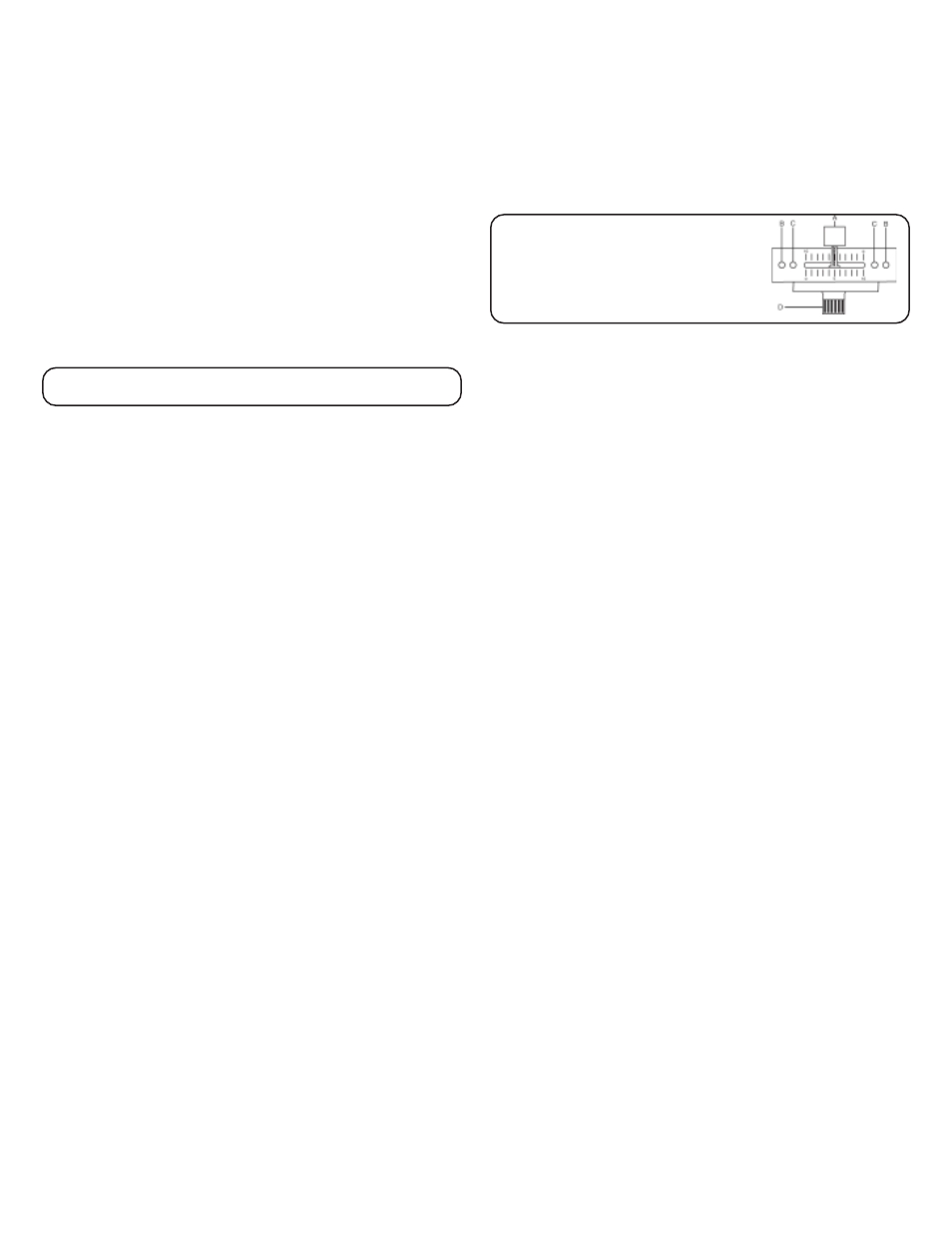
purchase one from your Gemini dealer and follow the instructions:
1. Unscrew the outside FADER PLATE SCREWS (B).
Do not touch the INSIDE SCREWS (C).
2. Carefully lift the fader and unplug the CABLE (D).
3. Plug the new fader into the cable and place it
back in the mixer.
4. Screw the fader to the mixer.
5. The CROSSFADER REVERSE SWITCH (27) allows you to reverse the
crossfader so that CHANNEL 2 is controlled by the left side of the
crossfader and CHANNEL 1 is controlled by the right side of the crossfader.
NOTE: WHEN THE CROSSFADER REVERSE SWITCH (27) IS ACTIVATED
(MOVED TO THE RIGHT), ONLY THE CROSSFADER REVERSES. THE
CHANNEL SLIDES, GAIN, AND TONAL CONTROLS DO NOT REVERSE.
6. PUNCH IN: The PUNCH IN BUTTONS (28) allow you to add a channel’s
signal to the mix when the crossfader is set to the opposite channel.
7. OUTPUT CONTROL SECTION: The level of the MASTER OUTPUT (3)
is controlled by the MASTER (29) control.
NOTE: THE RECORD OUT (4) HAS NO LEVEL CONTROL. THE LEVEL IS SET
BY THE CHANNEL SLIDES AND THE GAIN CONTROLS OF THE SELECTED
CHANNEL. THE TONAL QUALITIES ARE SET BY THE BASS, MID AND
HIGH CONTROLS OF THAT SAME CHANNEL.
8. TALKOVER SECTION: The purpose of the TALKOVER section is to
allow the program playing to be muted so that the MIC can be heard
above the music. The MIC/TALKOVER (30) switch has three settings.
When the MIC/TALKOVER (30) switch is in the left position, the MIC
and TALKOVER are both off. When the MIC/TALKOVER (30) switch
is in the center position the MIC is on, the MIC INDICATOR (31) will
glow, but talkover is off. When the MIC/TALKOVER (30) switch is in
the right position, the MIC and TALKOVER will be on and the volume of
all sources except the MIC input are lowered by 16 dB. MIC LEVEL
(33) controls the level of the MIC. The MIC EQ (32) control allows you to
fully adjust the tone of the MIC.
9. CUE SECTION: By connecting a set of headphones to the HEADPHONE
JACK (13), you can monitor either channel or both together. Move the
CUE SWITCH (34) to the left to monitor CHANNEL 1. Move the CUE
SWITCH (34) to the right to monitor CHANNEL 2. By rotating the CUE
PGM PAN (35) control to the left you will be able to monitor the assigned
cue signal. Rotating to the right will monitor the PGM (program) output.
Use the CUE LEVEL (36) control to adjust the headphone volume without
affecting the overall mix.
10.DISPLAY: DISPLAY (37) indicates the MASTER OUTPUT (3) left and right
levels, as controlled by the MASTER (29) level.
SPECIFICATIONS:
INPUTS:
DJ Mic........................................................................................1.5 mV 2 kOhm
Phono @1kHz...............................................................................2 mV 47 kOhm
Line.........................................................................................100 mV 10 kOhm
OUTPUTS:
Amp.........................................................................................0 dB 1V 400 Ohm
Max-18V Peak to Peak
GENERAL:
BASS (Channels 1-2)......................................................................+ 12 dB/-32 dB
Mid (Channels 1-2).........................................................................+ 12 dB/-32 dB
High (Channels 1-2).......................................................................+ 12 dB/-32 dB
Gain (Channels 1-2)............................................................................0 to -20 dB
Frequency Response...........................................................20 Hz-20 kHz +/- 2 dB
Distortion....................................................................................less than 0.02%
S/N Ratio..................................................................................better than 80 dB
Talkover Attenuation..................................................................................-16 dB
Power Source...............................................................Adapter-115V/15V AC 0.5A
..........................................................................................or
230V/15V AC 0.5A
Dimensions...............................................10” x 10.24” x 3.3” (254 x 260 x 84 mm)
Weight..........................................................................................6.25 lbs (3 kg)
Specifications and designs are subject to change without notice for the purpose of improvement.