Getting to know your belt and disc sander, Mounting belt and disc sander to workbench, Installing sanding disc and guard – Global Machinery Company BD1500 User Manual
Page 9: Installing work support
9
Getting to know your belt and disc sander
WARNING:
To avoid injury from accidental start, turn switch
’OFF’ and remove plug from power source outlet before
making any adjustments.
1. Work Support. Supports the workpiece on the
sanding belt.
2. Hex Socket Head Screw. Loosening screw allows belt
bed to be raised to the vertical position.
3. Tracking Knob. Turning knob anti-clockwise causes
sanding belt to move towards the disc. Turning knob
clockwise causes sanding belt to move away from
the disc.
4. Tension Lever. Sliding lever to the right releases the
sanding belt tension; sliding lever to the left applies
belt tension.
5. Table Lock Knob. Loosening knob allows the work table
to be tilted for bevel sanding.
6. Auxiliary Mounting Hole. Allows table assembly to
be mounted for end sanding when bed is placed in
vertical position.
Mounting belt and disc sander to workbench
If belt and disc sander is to be used in a permanent
location, it should be fastened securely to a firm supporting
surface such as a workbench.
If mounting to a workbench, holes should be drilled through
supporting surface of the workbench.
1. The unit should be bolted
securely using M8 screws and
hex nuts (not included). Screw
length should be 38mm plus
the thickness of the bench top.
2. Locate and mark the holes
where belt and disc sander is
to be mounted.
3. Drill (2) x 9.5 mm diameter holes though workbench.
4. Place belt and disc Sander on workbench aligning holes
drilled in workbench.
5. Insert two M8 screws and tighten hex nuts.
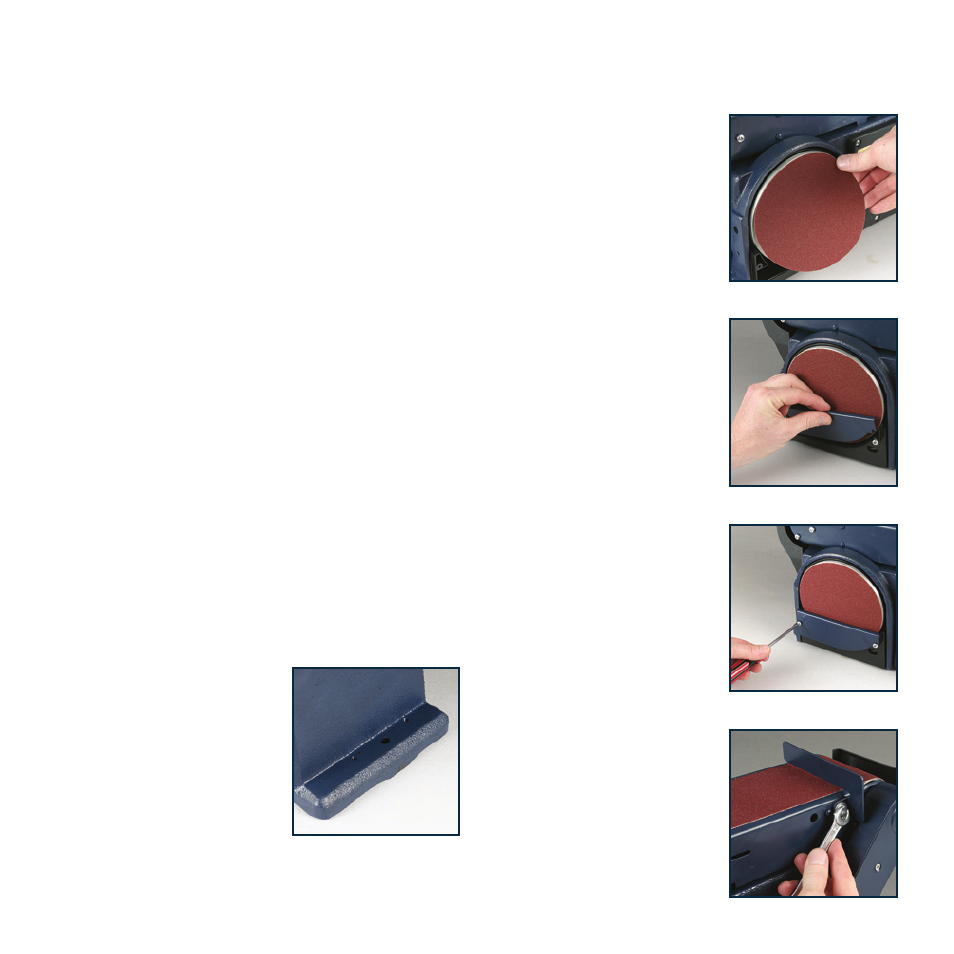
Installing sanding disc and guard
1. Remove the backing from
the sanding disc (7). Align
perimeter of disc with sanding
plate (8) and press disc
firmly into position all the way
around.
2. Locate disc guard (6) and two
M4.2 pan head screws.
3. Position disc guard against
lower 1/3 of disc aligning
holes.
4. Using a Phillips screwdriver,
fasten the pan head screws
securely, applying light
pressure to thread the holes.
Installing work support
1. Using a wrench secure
work support (9) to side
of belt & disc sander using
M6 hex screw, lock washer
and washer.
2. Hold work support in position
and fasten.