Troubleshooting – Greenheck Fan PVF User Manual
Page 7
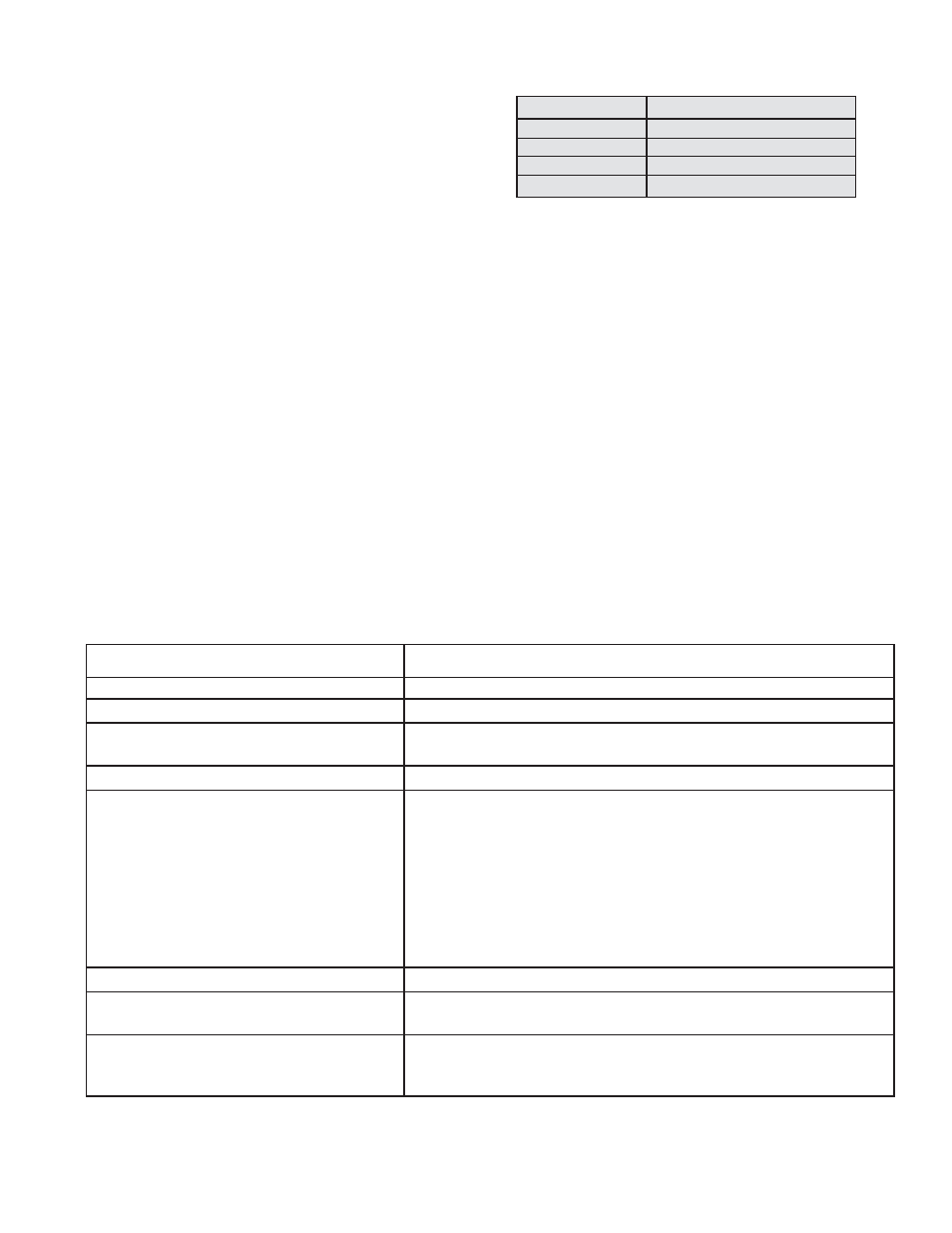
Ignition Control Diagnostic LED
During normal operation, the LED is shut off. The LED
will be on or flashing during a fault condition. If a fault
condition is occurring, turn the unit off and on again. If
the LED is still flashing, refer to the following
troubleshooting section.
LED Indication
Error Mode
Steady on
Internal control failure
1 flash
Air flow fault
2 flashes
Flame with no call for heat
3 flashes
Ignition lockout
Troubleshooting
Possible Cause
Solution
Manual gas valve not open
Open manual valve
Air in the gas line
Bleed gas line
Supply gas pressure too high or too low
Check that supply pressure is between 6 in. wg and 14 in. wg for
natural gas and 11 in. wg and 14 in. wg for LP.
Loose wire connections
Check for tight wire connections.
No spark:
a. Transformer failure
a. Check primary and secondary voltages of transformer. Replace
if necessary.
b. Spark electrode
b. Ensure spark gap is
1
⁄
8
in. and ceramic insulator is not cracked.
Replace if necessary. Electrode is NOT field-adjustable.
c. Spark cable shorted to ground
c. Replace spark cable
d. Ignition controller not grounded
d. Check that the ignition controller is grounded to the furnace
control center.
High limit control tripped
Check unit airflow and manifold pressure.
Faulty combination gas valve
If 24 volts is measured between terminals MV and common, but
valve remains closed, replace valve.
Faulty ignition control
Check diagnostic LED for steady on and for voltage between V1
and V2. If no voltage is present, replace ignition control.
Airflow Fault (1 Flash)
An airflow fault may occur for the following reasons:
• An airflow switch continually monitors the combustion airflow during an ignition sequence. During the initial
call for heat, if the pressure switch contacts are in the closed position for 30 seconds without an output to
the combustion blower, an airflow fault will be declared. The control will remain in this mode with the
combustion blower off.
• After the combustion blower output (L1 and IND) is energized and the airflow switch remains open for more
than 30 seconds, an airflow fault will be declared. The control will stay in this mode with the combustion
blower on, waiting for the airflow switch to close.
• If the airflow signal is lost while the burner is firing, the control will immediately de-energize the gas valve
and the combustion blower will remain on. If the call for heat remains, the control will wait for proper airflow
to return. If proper airflow is not detected after 30 seconds, an airflow fault will be declared. If proper airflow
is detected at any time, a normal ignition sequence will begin.
Once proper airflow is detected, the normal Sequence Of Operation for ignition will follow (see page 4).
Flame Fault (2 Flashes)
If the main valve fails to close completely and maintains a flame, the full-time flame sense circuit will detect it and
energize the combustion blower. Should the main valve later close completely and remove the flame signal, the
combustion blower will be de-energized.
Ignition Lockout (3 Flashes)
7