Furnace controls, Staged burner adjustments, Staged temperature controls performance data – Greenheck Fan PVF User Manual
Page 5
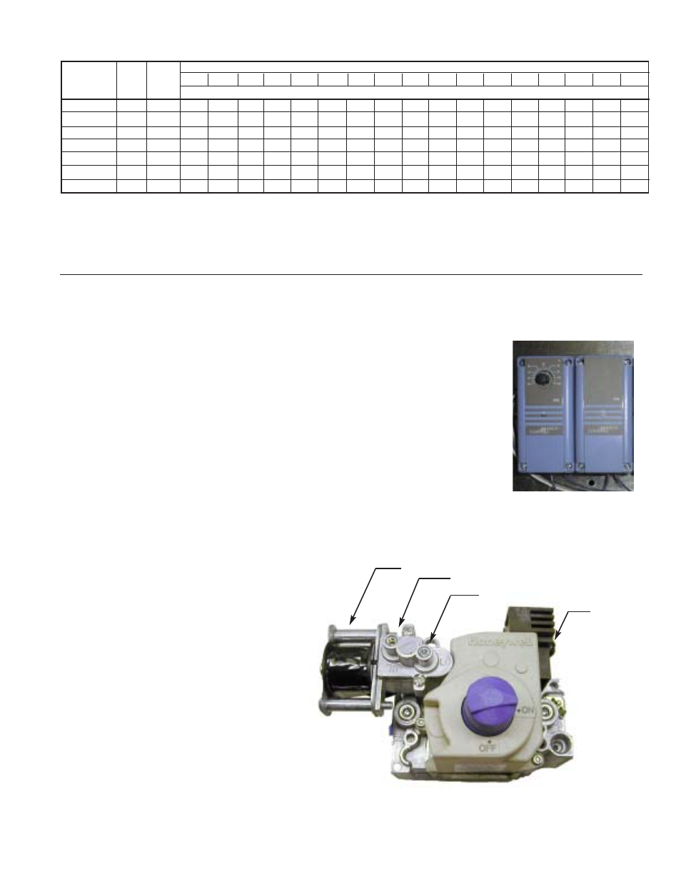
Setting Manifold Pressure for Two Stage Gas Control
1. Set the unit to high fire by setting the
discharge temperature control or
thermostat to its maximum setting. If the
ambient temperature is warm, the unit
may not stay at high fire.
2. Measure the burner manifold pressure at
the manifold pressure test port (see
Control Center Layout on page 3) using a
“U” tube manometer. The pressure on
high fire should be 3.5 in. wg for natural
gas and 10 in. wg for LP gas. To change
the pressure, adjust the regulator
adjustment screw on the combination gas
valve.
3. Set the unit to low fire by removing the
wire from the high fire terminal on the
combination gas valve.
4. The manifold pressure on low fire for natural gas
should be 0.88 in. wg and 2.5 in. wg for LP gas. To
change the pressure, use the low fire adjustment
screw on the combination gas valve.
Staged Burner Adjustments
Furnace Controls
For Energy Recovery Units without Temperature Control Package
The furnace stage controls are located in the furnace control center. One control is
provided for each stage of heating. The discharge temperature setting is located on
the control furthest to the left. The offset and differential settings for each stage are
preset at the factory; however, field-adjustments may be made to get the best control
for your application. See the literature provided with the controls for further
information.
For Energy Recovery Units with Temperature Control Package
If two-stage control is ordered with a Temperature Control Package, the controller in
the unit’s main control center will control the stages of heating. The temperature set
point may be adjusted on the controller (See Temperature Controller IOM).
Staged Temperature Controls
Performance Data
Ratings shown are for elevations up to 2000 ft. For higher elevations, the input should be reduced by 4% per 1000 ft. of
elevation above sea level. In Canada, from 2000 to 4500 ft in elevation, the unit must be derated to 90% of the input listed
above. The unit shall also be used in accordance with standard CGA 2.17.
High Fire Adjustment
Low Fire Adjustment
Solenoid
High Fire
Terminal
Air Temperature Rise Through Unit (°F)
Model
Input Output
20
25
30
35
40
45
50
55
60
65
70
75
80
85
90
95
100
Number
(MBH) (MBH)
CFM
PVF 100
100
80
3704
2963 2469 2116 1852
1646
1481 1347 1235
1140 1058
988
926
871
823
780
741
PVF 150
150
120
5556
4444
3704 3175 2778
2469
2222 2020 1852
1709 1587 1481 1389 1307 1235
1170 1111
PVF 200
200
160
7407
5926
4938 4233 3704
3292
2963 2694 2469
2279 2116 1975
1852 1743 1646
1559 1481
PVF 250
250
200
9259
7407
6173 5291 4630
4115
3704 3367 3086
2849 2646
2469 2315 2179 2058
1949 1852
PVF 300
300
240
11111 8889
7407 6349 5556
4938
4444 4040 3704 3419 3175 2963 2778 2614 2469
2339 2222
PVF 350
350
280
12963 10370 8642 7407 6481
5761
5185 4714 4321 3989 3704
3457 3241 3050 2881
2729 2593
PVF 400
400
320
14815 11852 9877 8466 7407
6584
5926
5387 4938 4558 4233
3951 3704 3486 3292 3119 2963
Figure 3: Staged Controls
Figure 4: Combination Gas Valve
5