Installation instructions, Thermal expansion, Location (cont.) – GE GEH50DXSRGA User Manual
Page 15
Installation Instructions
THERMAL EXPANSION
Determine if a check valve exists in the inlet water
line. It may have been installed in the cold water line as
a separate backflow preventer, or it may be part of a
pressure-reducing valve, water meter or water softener.
A check valve located in the cold water inlet line can
cause what is referred to as a “closed water system.”
A cold water inlet line with no check valve or backflow
prevention device is referred to as an “open” water
system.
As water is heated, it expands in volume and creates
an increase in the pressure within the water system.
This action is referred to as “thermal expansion.” In an
“open” water system, expanding water which exceeds the
capacity of the water heater flows back into the city main
where the pressure is easily dissipated.
A “closed water system,” however, prevents the
expanding water from flowing back into the main
supply line, and the result of “thermal expansion” can
create a rapid and dangerous pressure increase in the
water heater and system piping. This rapid pressure
increase can quickly reach the safety setting of the relief
valve, causing it to operate during each heating cycle.
Thermal expansion, and the resulting rapid and repeated
expansion and contraction of components in the water
heater and piping system, can cause premature failure of
the relief valve, and possibly the heater itself. Replacing
the relief valve will not correct the problem!
The suggested method of controlling thermal expansion
is to install an expansion tank in the cold water line
between the water heater and the check valve (refer to
the illustration on right). The expansion tank is designed
with an air cushion built in that compresses as the system
pressure increases, thereby relieving the over-pressure
condition and eliminating the repeated operation of
the relief valve. Other methods of controlling thermal
expansion are also available. Contact your installing
contractor, water supplier or plumbing inspector for
additional information regarding this subject.
15
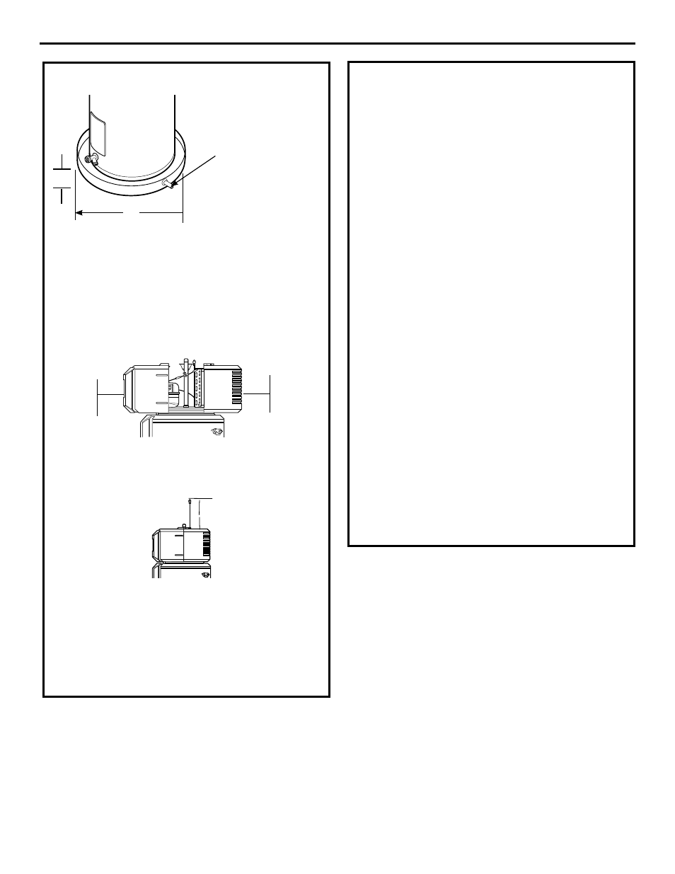
LOCATION (CONT.)
A— Diameter of water heater
plus 2” (5.1 cm) min.
B— Maximum 2” (5.1 cm)
NOTE: Auxiliary catch pan MuST conform to local codes.
Catch Pan Kits are available from the store where the water
heater was purchased, a builder store or any water heater
distributor.
Required clearances:
There must be a 5-1/2” (14 cm) minimum (7”/17.8 cm
recommended) clearance between any object and the Front
and Rear covers in the event service is needed. A minimum of
3” (7.6 cm) clearance with the sides of the water heater is also
recommended for service access.
A 14” (35.6 cm) minimum clearance is required to remove the
filter for cleaning. The hot and cold water plumbing
and electrical connections must not interfere with
the removal of the filter.
Condensation drain
The unit has a condensate drain; therefore a drain must be
available in close proximity to the unit. The drain must be no
higher than 36” (91.4 cm) above the floor (laundry drain is
acceptable).
If no drain is available, then a common condensate pump with
a capacity no less than 1 gallon (3.8 L)/day must be purchased
from a local builder supply store and installed.
B
A
Route to open drain. Line
should be at least 3/4”
(1.9 cm) ID and pitched
for proper drainage.
14” (35.6 cm)
5-1/2”
(14 cm)
5-1/2”
(14 cm)