Generac Power Systems Quietpact 75 User Manual
Page 57
S
Se
ec
cttiio
on
n 7
7
D
DIIA
AG
GN
NO
OS
ST
TIIC
C T
TE
ES
ST
TS
S
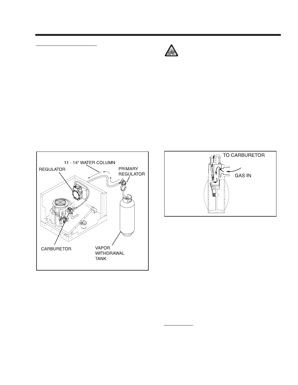
DISCUSSION (LPG MODELS):
LP gas is stored in pressure tanks as a liquid. The
gas systems used with these generators were
designed only for vapor withdrawal type systems.
Vapor withdrawal systems use the gas vapors that
form above the liquid fuel in the tank. Do NOT attempt
to use the generator with any liquid withdrawal type
system.
Gas pressure delivered to the solenoid valve must be
properly regulated by means of a primary gas regula-
tor. Mount the primary regulator at the gas tank outlet
or in the supply line from the gas tank. The following
rules apply:
• For best results, the primary regulator supplies
gaseous fuel to the secondary regulator at 11 inch-
es water column. Do NOT exceed 14 inches water
column.
• The installer must be sure the primary regulator is
rated at sufficient gas flow to operate the generator
plus all other gas appliances in the circuit.
Figure 7-27 – Typical Propane Gas Fuel System
NOTE: Recommended MINIMUM gas flow rate for
all air-cooled QUIETPACT series generators is 67
cubic feet per hour.
If an existing primary gas regulator does not have
a sufficient flow capacity for the generator and
other gas appliances in the circuit, (a) install a pri-
mary regulator with adequate flow rate, or (b)
install a separate regulator only and rated at least
67 cubic feet per hour. The inlet side of any prima-
ry regulator that supplies the generator must con-
nect directly to a gas pressure tank. Do NOT tee
the generator line into a gas circuit feeding other
areas.
C
CA
AU
UT
TIIO
ON
N!!:: U
Us
se
e o
on
nlly
y a
ap
pp
prro
ov
ve
ed
d c
co
om
mp
po
on
ne
en
ntts
s iin
n
tth
he
e ffu
ue
ell s
su
up
pp
plly
y s
sy
ys
stte
em
m.. A
Allll c
co
om
mp
po
on
ne
en
ntts
s m
mu
us
stt b
be
e
p
prro
op
pe
errlly
y iin
ns
stta
alllle
ed
d iin
n a
ac
cc
co
orrd
da
an
nc
ce
e w
wiitth
h a
ap
pp
plliic
ca
ab
blle
e
c
co
od
de
es
s.. IIm
mp
prro
op
pe
err iin
ns
stta
alllla
attiio
on
n o
orr u
us
se
e o
off u
un
na
au
utth
ho
o--
rriiz
ze
ed
d c
co
om
mp
po
on
ne
en
ntts
s m
ma
ay
y rre
es
su
ulltt iin
n ffiirre
e o
orr a
an
n e
ex
xp
pllo
o--
s
siio
on
n.. F
Fo
ollllo
ow
w a
ap
pp
prro
ov
ve
ed
d m
me
etth
ho
od
ds
s tto
o tte
es
stt tth
he
e s
sy
ys
s--
tte
em
m ffo
orr lle
ea
ak
ks
s.. N
No
o lle
ea
ak
ka
ag
ge
e iis
s p
pe
errm
miitttte
ed
d.. D
Do
o n
no
ott
a
allllo
ow
w ffu
ue
ell v
va
ap
po
orrs
s tto
o e
en
ntte
err tth
he
e v
ve
eh
hiic
clle
e iin
ntte
erriio
orr..
LP gas vapors should be supplied to the secondary
regulator inlet at about 11 inches water column (posi-
tive pressure). The engine pistons draw air in during
the intake stroke (Figure 7-28). This air passes
through a carburetor venturi, which creates a low
pressure that is proportional to the quantity of air
being pumped. The low pressure from the carburetor
venturi acts on the regulator diaphragm to pull the
diaphragm toward the source of low pressure. A lever
attached to the diaphragm opens a valve to permit
gas glow through the carburetor.
Figure 7-28 – LP Gas Carburetion Diagram
The greater the airflow through the carburetor venturi,
the lower the pressure at the venturi throat. The
lower the pressure at the venturi throat, the greater
the diaphragm movement, and the greater the move-
ment of the regulator valve. The more the regulator
valve opens, the greater the gas flow that is propor-
tional to airflow through the generator.
The following facts about the secondary regulator
must be emphasized:
• The regulator must be sensitive to venturi throat
pressure changes throughout the operating range.
• The regulator must be properly adjusted so it will
stop the flow of gas when the engine is not running
(no air flow through the carburetor).
• The slightest airflow (and vacuum in the venturi
throat) should move the regulator valve off its seat
and permit gas to flow.
PROCEDURE:
A water manometer or a gauge that is calibrated in
“ounces per square inch” may be used to measure
the fuel pressure. Fuel pressure at the inlet side of the
LPG Shut Off Valve should be between 11-14 inches
Page 55