Exhaust venting, Water supply – GSW 72090 User Manual
Page 11
Exhaust Venting
Vent Pipe System
This water heater is a Category 1, non-direct vented appli-
ance.
The vent pipe must be installed in accordance with all local
and provincial or state codes or, in the absence of such
codes, with the latest edition of “Natural Gas and Propane
Installation Code” CAN/CSA-B149.1
in Canada,
“National Fuel Gas Code” ANSI Z223.1 (NFPA 54) in the
U.S.A. The vent pipe must not be obstructed so as to pre-
vent the removal of exhaust gases to the outside atmos-
phere.
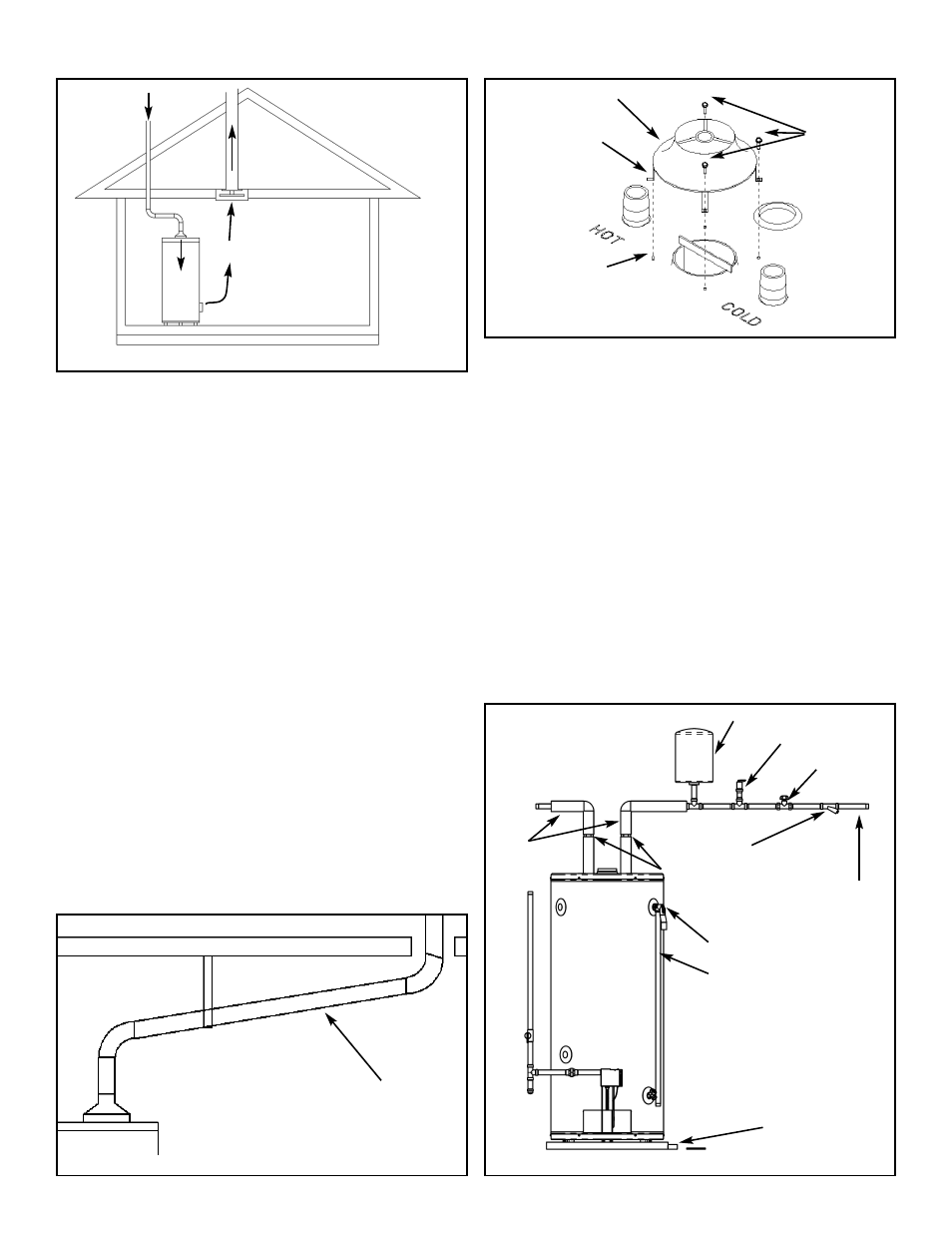
Note: The horizontal section of the vent must slope up
21mm per metre (1/4 in. per foot), (see Figure 8).
U.L. recognized fuel gas and carbon monoxide (CO) detec-
tors are recommended in all applications and should be
installed using the manufacturer’s instructions and local
codes, rules or regulations.
Important: If you lack the necessary skills required to prop-
erly install this venting system, you should not proceed, but
enlist the help of a qualified service technician.
Drafthood Installation
Hook the tab leg of the drafthood into the slot in the heater’s
top. Align the remaining legs with the hole/dimples and
secure the drafthood to the top with three screws as shown
in Figure 9. Do not alter the drafthood in any way. If you are
replacing an existing water heater be sure to use the new
drafthood supplied with the water heater.
Water Supply
Piping Installation
Piping, fittings, and valves should be installed according to
the installation drawing (Figure 10). If the indoor installation
area is subject to freezing temperatures, the water piping
must be protected by insulation. Water supply pressure
should not exceed 550 kPa (80psi). If this occurs a pressure
reducing valve and/or an expansion tank may be required.
The pressure reducing valve should be placed on the sup-
ply to the entire house in order to maintain equal hot and
cold water pressures.
Important: Heat must not be applied to the water fittings on
the heater as they may contain nonmetallic parts. If solder
connections are used, solder the pipe to the adapter before
attaching the adapter to the hot and cold water fittings.
Install the water piping and fittings as shown in Figure 10.
Connect the cold water supply to the fitting (3/4” NPT)
marked “COLD” (or “C”). Connect the hot water supply to
the fitting (3/4” NPT) marked “HOT” (or “H”).
REVERSE
FLOW OF
GASES
EXHAUST
FAN
Figure 7 Air Moving Devices
SLOPE UP 21mm PER METRE
(1/4 in. PER ft) MIN.
Figure 8 Vent System
DRAFTHOOD
Figure 9 Drafthood Installation
TAB LEG
SLOT
SCREW
Figure 10 Example Of Water Piping Installation
IN A CLOSED SYSTEM USE EITHER:
1.THERMAL EXPANSION TANK
2.PRESSURE RELIEF VALVE
COLD WATER
INLET VALVE
UNION
PRESSURE REDUCING
VALVE WITH BYPASS
COLD WATER
INLET
T E M P E R A T U R E A N D
PRESSURE RELIEF VALVE
DISCHARGE LINE 300mm
(12 in.) MAX (CANADA) OR
150mm (6 in.) MAX (U.S.A.)
ABOVE DRAIN
M A S S A C H U S E T T S :
I N S TA L L A VA C U U M
RELIEF IN COLD WATER
L I N E P E R S E C T I O N
19MGL 142
DRAIN LINE 19mm
(3/4 in.) ID MIN
HOT WATER
OUTLET
PIPE
INSULATION
– 11 –