Grindmaster 3312 User Manual
Page 10
CARE AND CLEANING
Drain and Rinse (cont.)
4. Remove the carburetor tube and pour water into the storage hopper. Allow the water to fill the freezing cylinder.
5. Turn the panel switch to “CLEAN” for 5 minutes.
6. Open the dispensing valve and drain the water from the freezer.
7. Turn the freezer “OFF”.
Disassembly and Cleaning
Note: For cleaning and sanitizing before initial start-up remove carb tubes, dispense plungers, handles and springs
from parts bag first.
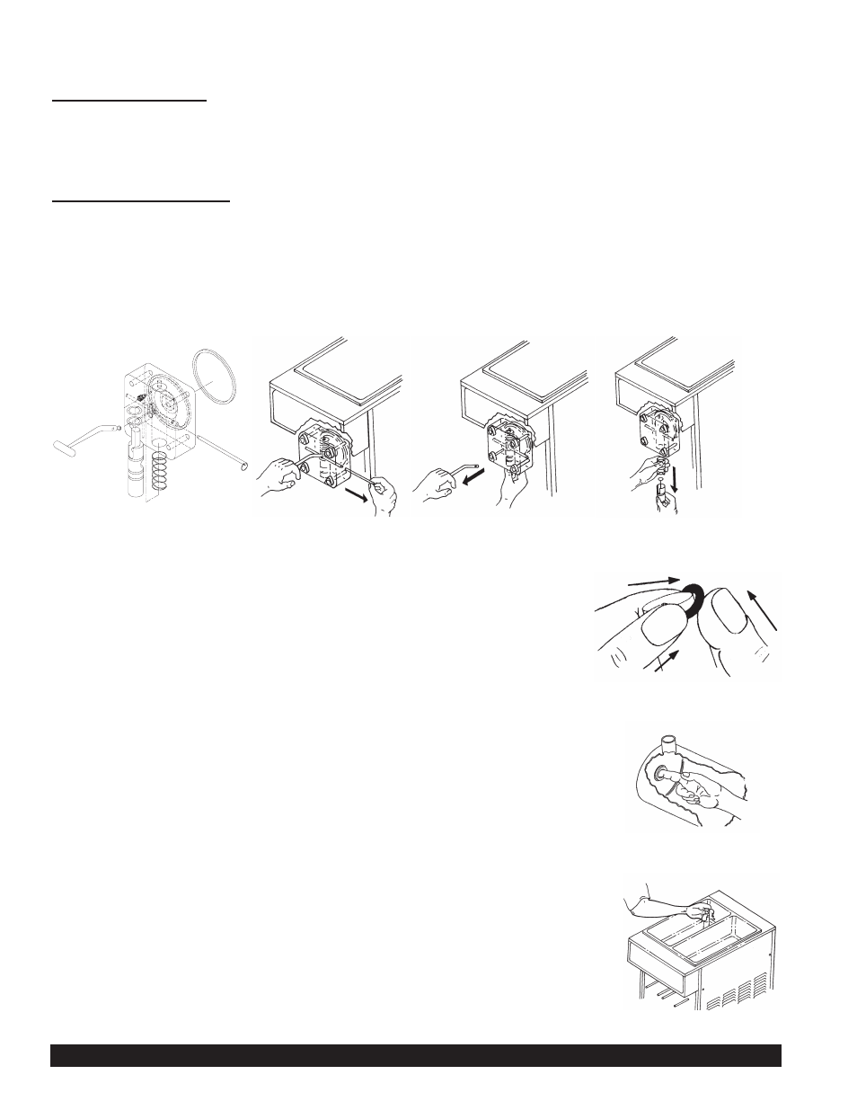
1. Disassemble the dispensing valve assembly (Figure M). Pull out valve handle retaining pin while supporting the
valve plunger from the bottom (Figure N). Push up on the valve plunger and remove the stainless handle
(Figure O). Slide the valve plunger and spring downward to remove (Figure P).
2. Remove knobs and carefully remove the front dispensing valve assembly, leaving the dasher assembly in the
cylinder. Remove the o-rings from the plunger assembly and back of the dispensing valve body. (See Figure Q)
NOTE: The best way to remove an o-ring is to first wipe off all of the lubricant using a
clean paper towel. Pinch the o-ring upward with a dry paper towel between your index
finger and thumb. When a loop is formed in the o-ring, roll it out of the groove with
your other thumb. Always remove the o-ring farthest from the end of the plunger first.
Carefully inspect the o-rings and replace if necessary.
(See Figure Q)
3. Remove the dasher assembly from inside the freezing cylinder taking care to avoid
damaging the rear seal assembly at the back of the freezing cylinder. Disassemble
the dasher assembly by removing the stator rod and front and rear stator rod
bearings.
4. Remove stationary half of the shaft seal assembly from the back end of the
freezer cylinder. This is accomplished by reaching into the cylinder and pulling seal
out with your index finger. (See Figure R)
5. Slide the rotary half of the seal off the dasher shaft. Inspect both seal components
carefully for nicks or cracks. Replace seal if defective.
NOTE: To prevent leakage the surfaces of the rotary seal and the stationary seal must be
smooth with no chips or cracks.
NOTE: All units are shipped with a standard ceramic seal (Part # W0340201) unless
otherwise specified. Certain products contain coconut oil which requires a different sealing
material. For these products use the coconut oil seal (Part # W0340210). The stationary
half of the standard seal has a white polished surface. The stationary half of the coconut oil
seal has a glossy black surface.
6. Remove carb tube from bottom of hopper and remove o-rings. (See Figure S).
7. Repeat disassembly procedures on other side.
Figure N Remove Pin
Figure M Disassemble
Dispensing Valve
Figure O Remove Handle
Figure P Remove
Plunger and Spring
Figure Q Ring Removal
Page 8
Model 3312
Figure R Remove the
stationary half of seal
Figure S Carb Tube