Part 4, Description and components – Generac Power Systems 8 kW LP User Manual
Page 100
PiN
WirE
circuit fuNctioN
J1-1
85
High temperature shutdown:
Shutdown occurs when Wire 85 is
grounded by contact closure in HTO
J1-2
86
Low oil pressure shutdown: Shutdown
occurs when Wire 86 is grounded by
loss of oil pressure to the LOP
J1-3
13
12 VDC source voltage for the circuit
board
J1-4
18
Ignition Shutdown: Circuit board
action grounds Wire 18 for ignition
shutdown.
J2-1
0
INTERNAL USE
J2-2
0
INTERNAL USE
J2-3
14
12 VDC output for engine run condi-
tion. Used for fuel solenoid.
J2-5
23
Switched to ground for transfer relay
operation
J2-6
NOT USED
PiN
WirE
circuit fuNctioN
J2-7
NOT USED
J2-8
15B
Provides an electrical connection for
charge current to reach the battery
from the battery charger. Provides
12VDC to the Transfer Relay
J2-9
NOT USED
J2-10
0
Common Ground
J2-11
56
12 VDC output to starter contactor for
single cylinder engines.
J2-15
NOT USED
J2-16
NOT USED
J2-17
NOT USED
J2-18
NOT USED
Wired Plug 1
N1
240 VAC sensing for control board.
Wired Plug 2
N2
240 VAC sensing for control board.
Page 98
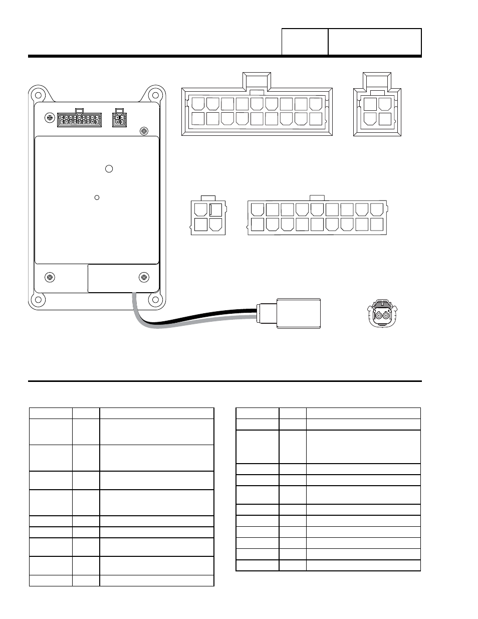
8 kW J1 connector Pin Descriptions
J2
J1
J2 CONNECTOR
(HARNESS END)
N1/N2 CONNECTOR
(HARNESS END)
N1/N2 CONNECTOR
(PCB END)
10 11 12 13 14 15 16 17 18
1
2
3
4
1
2
3
4
5
6
7
8
9
10
11
12
13
14
15
16
17
18
1
2
3
4
1
2
3
4
5
6
7
8
9
10
11
12
13
14
15
16
17
18
1
2
3
4
1
2
3
4
5
6
7
8
9
J1 CONNECTOR
(HARNESS END)
J2 CONNECTOR
(PCB END)
J1 CONNECTOR
(PCB END)
1
2
Figure 4. 8 kW Printed Circuit Boards and J1 Connector
Part 4
DC CONTROL
sEctioN 4.1
DEscriPtioN aND comPoNENts