2 insulation resistance riso, Insulation resistance r – Gossen MetraWatt 702 User Manual
Page 17
GOSSEN METRAWATT GMBH
17
Combined Test – Differential Protective Conductor Resistance
Zero balancing is also possible for protective conductor measurement. With
zero balancing, all subsequent measurements are adjusted with an offset
such that 0
Ω is displayed for a selected reference point which is
connected to the protective conductor. When test points are contacted
with the probe which are electrically connected to this reference point, dif-
ferential resistance
ΔR
PE
between the reference point and the contacted
test point is displayed.
The mains release key
must be activated during measurement in order
to perform zero balancing. The acquired value can either be applied (the
value remains in memory until the instrument is disconnected from mains
power), permanently saved or deleted.
Maximum Allowable Limit Values for Protective Conductor Resistance
for Connector Cables with Lengths of up to 5 m
1)
This value may not exceed 1
Ω
for permanently connected data processing
systems (DIN VDE 0701, part 240).
2)
Total protective conductor resistance: max. 1
Ω
9.2
Insulation Resistance R
ISO
.
Definition
Safety Class I
Insulation resistance is
measured between short-
circuited mains terminals and
the protective conductor.
Safety Classes II and III
Insulation resistance is
measured between short-
circuited mains terminals and
external conductive parts
which can be contacted with
the probe.
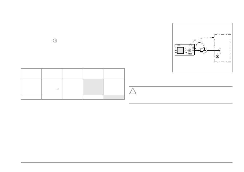
Exception for Permanently Installed Safety Class I Devices
Attention!
!
Deactivate the electrical system which supplies power to the
device under test before connecting the test instrument!
➭ Remove the mains fuses from the device under test and disconnect
the neutral conductor N inside the device under test.
➭ Connect the probe to phase conductor L at the device under test in
order to measure insulation resistance.
Test Standard
Test Current
Open-
Circuit Voltage
R
PE
Housing –
Device Plug
R
PE
Housing –
Mains Plug
VDE 0701
Part 1:2000
VDE 0702:2004
VDE 0751:2001
> 200 mA
4 V < U
L
< 24 V
0.3
Ω
1)
+ 0.1
Ω
2)
for each
additional 7.5 m
VDE 0751:2001
0.2
Ω
Ω
for S
C II