9 individual measurements, 1 measuring protective conductor resistance, Individual measurements – Gossen MetraWatt 702 User Manual
Page 16: Measuring protective conductor resistance
16
GOSSEN METRAWATT GMBH
9
Individual Measurements
9.1
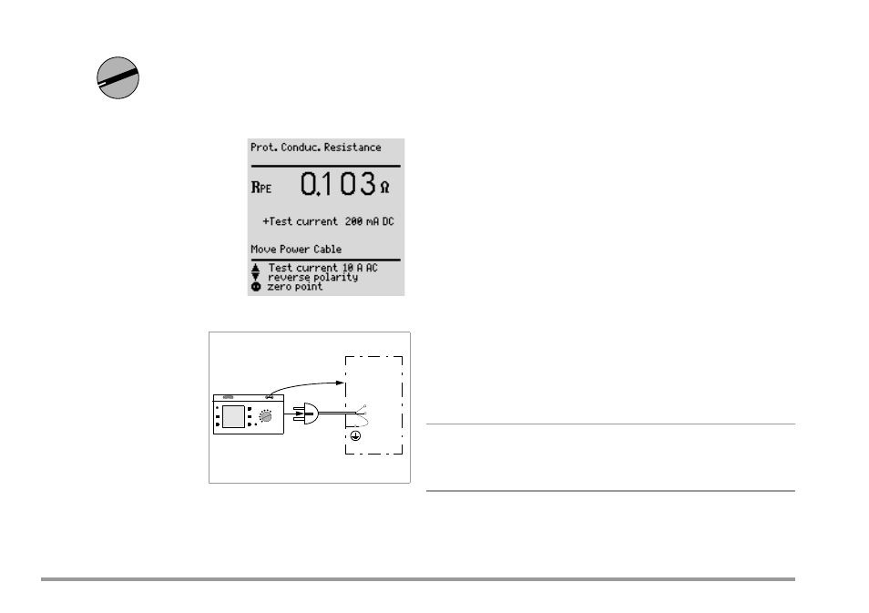
Measuring Protective Conductor Resistance
Definition
Protective conductor resistance
is the sum of the following
resistances:
•
Connector cable or device
connector cable resistance
•
Contact resistance at plug
and terminal connections
•
Extension cable resistance if
utilized
Resistance is measured:
•
Between each exposed conductive part of the housing and the
earthing contacts at the mains and the device plug (if a removable
mains connector cable is used), or the protective conductor terminal
for permanently installed devices.
•
As a 4-pole measurement
•
Between the earthing contacts at the mains plug and the earthing
contacts at the device plug for device connector cables
•
Between the earthing contacts at the mains plug and the earthing
contacts at the coupling socket for extension cables
Connecting Safety Class I Devices to the Test Socket
When the DUT is connected, resistance is measured between the protec-
tive conductor terminal at the test socket or at the PE jack, and the probe
connection at the DUT (contact with conductive parts of the housing).
➭ In order to measure protective conductor resistance, contact a
conductive part of the housing with the probe, which is connected
to the protective conductor.
During measurement, the connector cable must only be moved to the
extent it is accessible during repair, modification or testing.
If a change in resistance occurs during the manual test step of the conti-
nuity test, it must be assumed that the protective conductor is damaged,
or that one of the connector contacts is no longer in flawless condition.
Testing Extension Cables
See test sequence in chapter 11.7 on page 34.
Note
☞
“DUT connection: SC I/II” is not displayed when the test is
performed individually, but rather only during the automatic test
sequence.
MENU
Ω