Gsd 20 – Garmin GSD-20 User Manual
Page 5
3
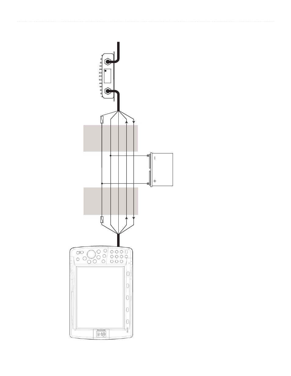
GSD 20 Sonar Module
I
NSTALLATION
I
NSTRUCTIONS
W
IR
E
C
O
LO
R
GARMIN GSD 20
SOUNDER MODULE
BL
AC
K
O
R
AN
G
E
R
ED
W
H
IT
E/
BL
U
E
BL
AC
K
R
ED
W
H
IT
E/
BL
U
E
W
H
IT
E/
BR
O
W
N
W
H
IT
E/
BR
O
W
N
W
IR
E
C
O
LO
R
5
A
FU
SE
O
R
AN
G
E
2
A
FU
SE
TO
TRANSDUCER
BA
TT
ER
Y
10
-3
5
VO
LT
S
D
C
B
ASIC
W
IRING
FOR
THE
G
ARMIN
GSD 20
TO
A
S
INGLE
GPSMAP
2006/2006C/2010/2010C/3005C/3006C/3010C
Notes:
1.
Power and ground wires require 18
AWG.
All other wires require 22
AWG. Use 4-conductor
, shielded wiring for runs over 30’
(9.1 m).
2.
Refer to the GPSMAP
2006/2006C/2010/2010C/3005C/3006C/3010C Installation Instructions for wiring the GPS 17 sensor and other devices.
3.
For runs over 30’
(9.1 m), the drain wire must be connected to the shielding of the extension run. Do not terminate the end of the shield drain wire.
4.
When multiple GPSMAP
3005C/3006C/3010C units are in use, only wire the GSD 20 to one unit.
The GSD 20 information is transmitted to all
units connected to the Garmin Marnine Network.
- GMR 406 (26 pages)
- 340c (2 pages)
- GHP 10 (48 pages)
- GMR 1204 (14 pages)
- GMR24 Hd (12 pages)
- 190-00864-01 (24 pages)
- GFS 10 (24 pages)
- GMR 40 (32 pages)
- GMI 10 (8 pages)
- GMI 10 (20 pages)
- 240 (50 pages)
- Hiking Equipment (2 pages)
- GHS 10i (10 pages)
- G2 (24 pages)
- 100 BLUE (50 pages)
- GTX 320 ATC (24 pages)
- 80 (2 pages)
- GMR 41 (32 pages)
- 160 BLUE (50 pages)
- 250C (1 page)
- VHF 200 (10 pages)
- GPSMAP 2008 (124 pages)
- GMR 41 (26 pages)
- 160 (50 pages)
- Gxm 51 (10 pages)
- 160C (32 pages)
- Nuvi 900 (16 pages)
- GSD22 (8 pages)
- 90/140 (32 pages)
- VHF 200 (2 pages)
- Ghc 10 (28 pages)
- GSD 22 (10 pages)
- GPSMAP 3010C (2 pages)
- GPSMAP 3010C (130 pages)
- GPSMAP 76CSx (64 pages)
- GPSMAP 76CSx (2 pages)
- GPSMAP 76S (76 pages)
- GPSMAP 76S (18 pages)
- GPSMAP 172C (110 pages)
- GPSMAP 3005C (124 pages)
- GPSMAP 3005C (2 pages)
- GPSMAP 276C (2 pages)
- GTX 328 (10 pages)
- GPSMAP 526s (84 pages)