7 engine governor adjustment, 8 voltage regulator adjustment – Generac Power Systems 05176-0 User Manual
Page 15
13
Section 3 — Post Installation Start-up and Adjustments
Air-cooled 15 kW Generators
7. Turn utility power to the main distribution panel
back on. This can be done by switching the ser-
vice main breaker to the on or closed position.
Allow the generator to shut down.
Do not make any unnecessary adjustments.
Factory settings are correct for most applica-
tions. However, when making adjustments, be
careful to avoid overspeeding the engine.
If this procedure or equipment are not available,
locate the nearest Service Dealer and they can per-
form the adjustments.
NOTE:
A service fee may be charged for this adjustment.
3.7 ENGINE GOVERNOR ADJUSTMENT
If both AC frequency and voltage are correspondingly
high or low, adjust the engine governor as follows:
1. Loosen governor clamp bolt (See Figure 3.3).
Figure 3.3 — V-twin Engine Governor
Adjustment
Governor Clamp Bolt
Governor
Shaft
(Rotate
Clockwise)
Idle Spring
No Load Idle
Adjustment Screw
2. Completely remove the idle spring.
3. With governor arm at wide open throttle position,
rotate governor shaft fully clockwise. Tighten
clamp bolt to 84 inch-pounds.
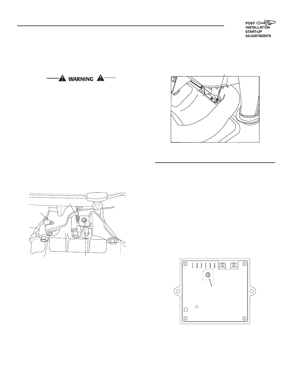
4. Start unit and apply full load. Use full load speed
adjust screw (Figure 3.4) to adjust frequency to
58 Hz.
5. Remove load, stop engine, loosen the idle adjust
screw and reconnect the idle spring.
6. Using a hand, push the governor arm to the
closed throttle position. Make sure the idle spring
does not stretch at all.
7. Restart
the
unit.
8. Slowly turn the idle adjust screw to adjust the no-
load idle frequency to 63-63.5 Hz.
9. The governor is now set.
Figure 3.4 — V-twin Full Load Speed Adjust
Screw
Full Load Speed Adjust Screw
3.7.1
ADDITIONAL CORROSION
PROTECTION
Periodically spray all engine linkage parts and brack-
ets with corrosion inhibiting spray such as WD-40
®
or a comparable product.
3.8
VOLTAGE REGULATOR
ADJUSTMENT
With the frequency between 62-63.5 Hertz, slowly
turn the slotted potentiometer (Figure 3.5) until line
voltage reads 244-252 volts.
NOTE:
Remove the access panel on top of the control
panel to adjust the voltage regulator.
Figure 3.5 – Voltage Adjustment Potentiometer
Turn to
adjust voltage.
NOTE:
The voltage regulator is housed above the generator's
control panel. The regulator maintains a voltage in
direct proportion to frequency. For example, at 62
Hertz, line-to-neutral voltage will be 124 volts.