Generac Power Systems 05176-0 User Manual
Page 10
Remote monitoring functions are only available with
the AUTO/OFF/MANUAL switch in the Auto or Manual
position. Since the contacts are SPDT, it is possible
to monitor either state of each alarm function.
Relay 1: Engine running, normally closed.
Engine not running, normally open
Relay 2: Transfer Switch in Emergency, normally
closed
Transfer Switch in Utility, normally open
Relay 3: Control panel switch in Auto, normally
open
Control panel switch in Manual or Off, nor-
mally closed
Relay 4: The common alarm is activated by any of
the following shutdown faults
Low Oil Pressure
High Engine Temperature
Overspeed
Overcrank
Common alarm active, normally open
No Common alarm, normally closed
Relay 5: Spare, not used on this model
Relay 6: Enclosure door open, normally closed
Enclosure door closed, normally open
2.1.2 ROOF OPEN ALARM
This generator is equipped with an alarm to detect
when the roof of the enclosure is open. A limit switch
that is installed in the generator enclosure controls
this alarm. During shipping, the generator's enclosure
panels may have shifted and this limit switch may
require adjustment. Simply loosen the two screws
and adjust the placement of the limit switch. The arm
of the limit switch should be in the depressed posi-
tion when the enclosure roof is closed and the door
latch is secure (see Figure 2.2).
Figure 2.2 — Limit Switch
Up
Down
Slots
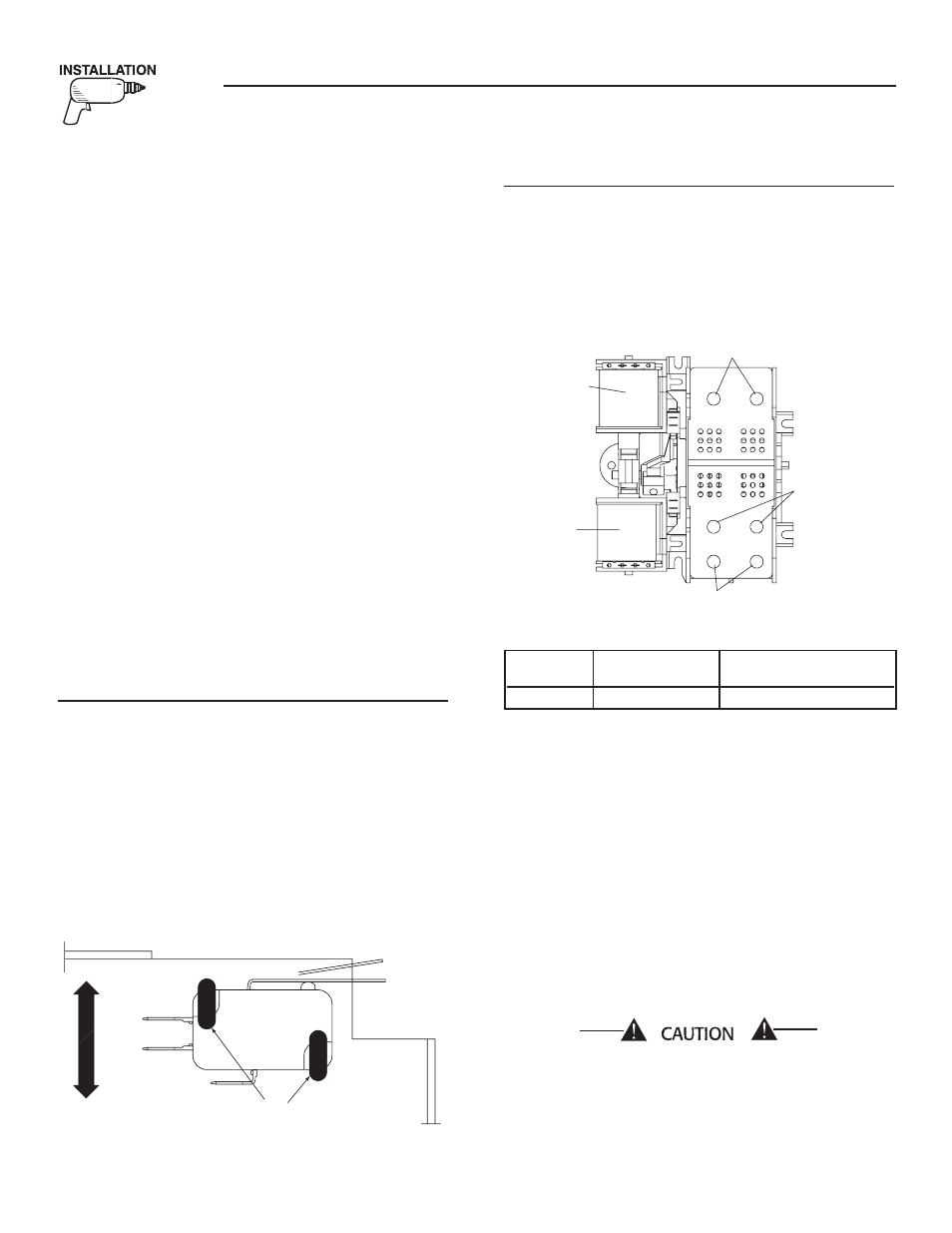
2.1.3 TRANSFER SWITCH CONNECTION
These switches (Figure 2.3) are used with a single-
phase system, when the single-phase NEUTRAL line
is to be connected to a Neutral Lug and is not to be
switched.
Figure 2.3 — Typical 2-Pole Transfer Mechanism
(200 Amp Shown)
UTILITY
CLOSING
COIL
GENERATOR
CLOSING
COIL
UTILITY LUGS
GENERATOR
LUGS (E1 & E2)
LOAD LUGS (T1 & T2)
Solderless, screw-type terminal lugs are standard.
Conductor sizes must be adequate to handle the
maximum current to which they will be subjected to,
based on the 75°C column of tables, charts, etc. used
to size conductors. The installation must comply fully
with all applicable codes, standards and regulations.
Before connecting wiring cables to terminals, remove
any surface oxides from the cable ends with a wire
brush. All power cables should enter the switch next
to transfer mechanism terminals. If ALUMINUM con-
ductors are used, apply corrosion inhibitor to con-
ductors. Tighten terminal lugs to the torque values as
noted on the decal located on the inside of the door.
After tightening terminal lugs, carefully wipe away
any excess corrosion inhibitor.
All power cables should enter the switch next to the
transfer mechanism terminals.
Use a torque wrench to tighten the conductors,
being sure not to over tighten, or damage to
the switch base could occur. If not tightened
enough, a loose connection would result, caus-
ing excess heat which could damage the switch
base.
Section 2 — Installation
Air-cooled 15 kW Generators
8
Switch Wire Conductor
Tightening
Rating
Range
Torque
200A
#6-250 MCM
275 in-lbs.