Jb2 ja2, Ja jb – GE 225 User Manual
Page 31
g
GE
OPM_SGS_ISG_M22_M30_0US_V011.doc
31/38
Installation
Guide
SG Series 225 & 300 kVA
SGT5000_100-150_RPA-IM0048_02
JP3
JP1
JP4
IM 0048
JP2
JP1
JP2
JP4
JP3
JB1
JA1
JB
JA
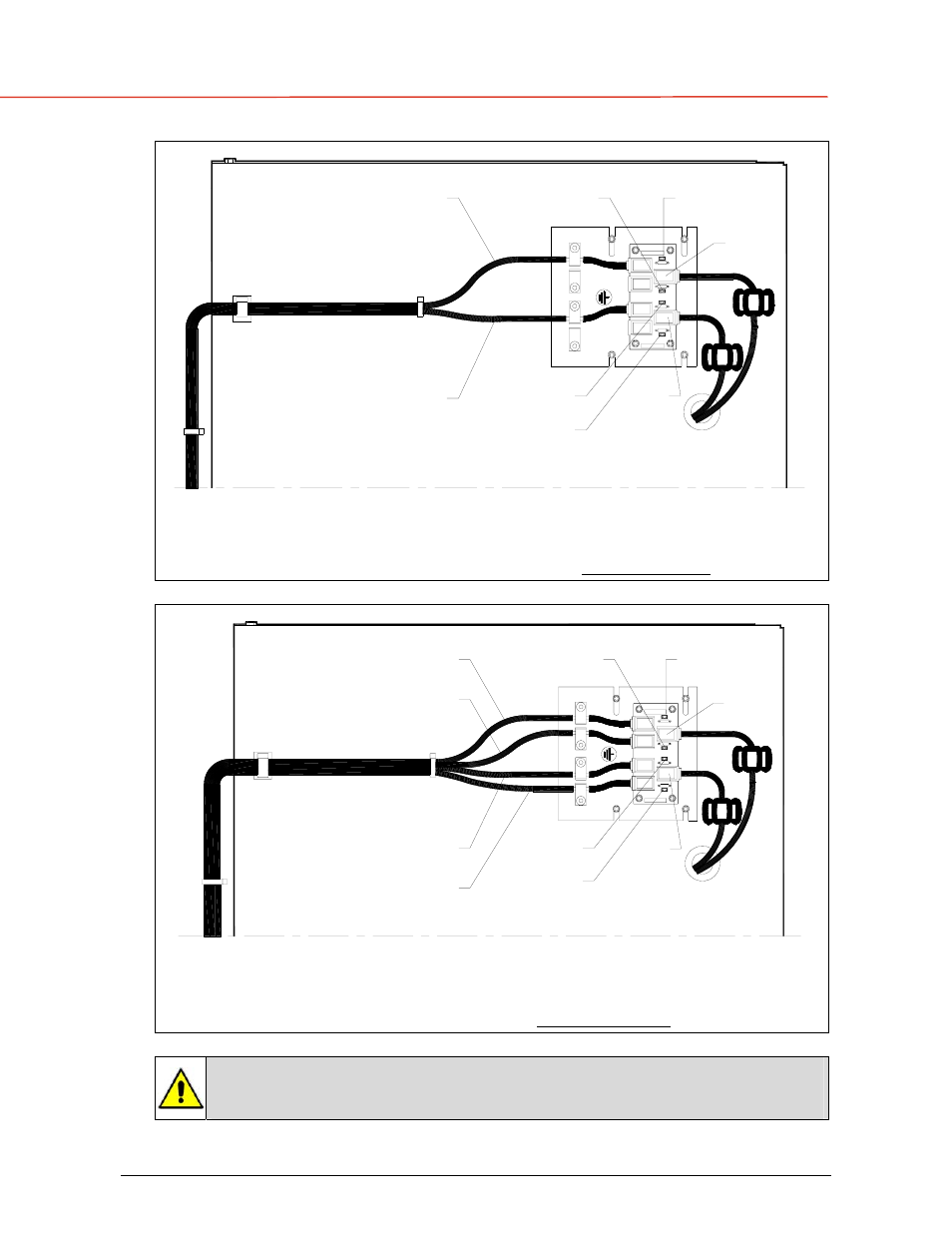
Fig. 3.10-2 Bus connection on terminal units
Terminal units
On the parallel bus PCB “P34 – Bus Interface IM0048”, of the first and last units (terminal)
of the parallel system the Jumpers JP1, JP2, JP3 and JP4 must be inserted.
JB1
JA1
JP2
JP1
JP3
JP4
JP3
JP2
JP1
JP4
IM 0048
JB2
JA2
SGT5000_100-150_RPA-IM0048_03
JA
JB
Fig. 3.10-3 Bus connection on intermediate units
Intermediate units
On the parallel bus PCB “P34 – Bus Interface IM0048” of the intermediate units of the
parallel system the Jumpers JP1, JP2, JP3 and JP4 must be removed.
In a parallel system composed of 2 or more units, only the first and last units
(having 1 input JA and JB free) have the Jumper JP1, JP2, JP3 and JP4 inserted on
parallel bus PCB “P34 – Bus Interface IM0048” (see Fig. 3.10-2).