5 connecting start circuit wires, 6 auxiliary contacts – Generac Power Systems 04635-0 User Manual
Page 6
4
Generac
®
Power Systems, Inc.
Use a torque wrench to tighten the
conductors, being sure not to overtighten, or
damage to the switch base could occur. If
undertightened, a loose connection would
result, causing excess heat which could
damage the switch base.
Connect power source load conductors to clearly
marked transfer mechanism terminal lugs as follows
1. Connect UTILITY (NORMAL) power source cables
to switch terminals N1, N2.
2. Connect EMERGENCY (STANDBY) source power
cables to transfer switch terminals E1, E2.
3. Connect customer LOAD leads to switch
terminals Load 1, Load 2. (Load 1 and Load 2 are
used with liquid-cooled units only.)
Conductors must be properly supported, of approved
insulative qualities, protected by approved conduit,
and of the correct wire gauge size in accordance with
applicable codes.
Be sure to maintain proper electrical clearance
between live metal parts and grounded metal. Allow
at least 1/2 inch for 100-400 amp circuits; at least
one inch for circuits over 400 amps.
2.5
CONNECTING START CIRCUIT
WIRES
Control system interconnections consist of UTILITY
1 and 2, LOAD 1 and 2 (liquid-cooled units only); and
leads 23 and 194. Control system interconnection
leads must be run in a conduit that is separate from
the AC power lead. Recommended wire gauge sizes
for this wiring depends on the length of the wire, as
recommended below:
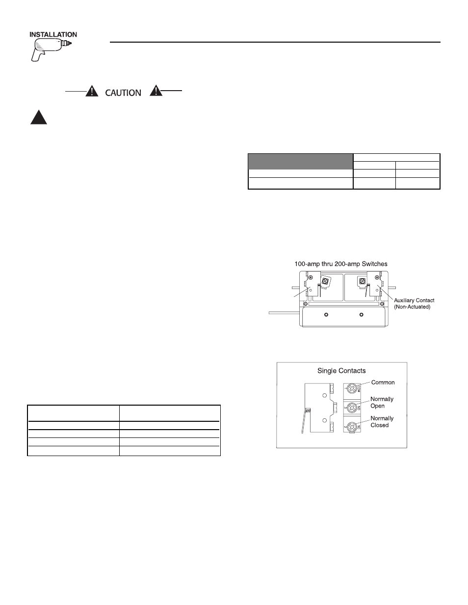
2.6 AUXILIARY
CONTACTS
If desired, there are Auxiliary Contacts on the
transfer switch to operate customer accessories,
remote advisory lights, or remote annunciator
devices. A suitable power source must be connected
to the COMMON (C) terminal. See Figure 2.3.
Contact operation is shown in the following chart:
NOTE:
Auxiliary Contacts are rated 10 amps at 125 or
250 volts AC. DO NOT EXCEED THE RATED
VOLTAGE AND CURRENT OF THE CONTACTS.
Figure 2.3 – Auxiliary Contacts
Optional
Auxiliary Contact
(Actuated)
Side views shown in Utility position
!
Section 2 — Installation
Generac GTS “W” Type Transfer Switch
MAXIMUM WIRE LENGTH
RECOMMENDED WIRE
SIZE
460 feet (140m)
No. 18 AWG.
461 to 730 feet (223m)
No. 16 AWG.
731 to 1,160 feet (354m)
No. 14 AWG.
1,161 to 1,850 feet (565m)
No. 12 AWG.
Switch Position
Utility
Standby
Common to Normally Open
Open
Closed
Common to Normally Closed
Closed
Open