4 jumpers and led’s – FUJITSU ADA-16FX User Manual
Page 8
ADA-16FX-ETHERNET
Chapter 4 Jumpers and LED’s
UG-960011-11
- 8 -
© Fujitsu Microelectronics Europe GmbH
4 Jumpers and LED’s
This chapter describes all jumpers that can be modified and all LED’s on the adapter board.
The default setting is shown with a grey shaded area.
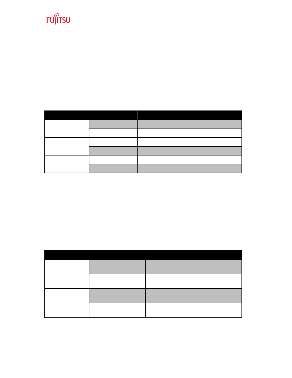
4.1 Chip select (JP: 1, 2, 3)
One out of the three chip select signals CS2, CS3 or CS4 can be selected:
JP1, JP2, JP3 connect chip select signal of MCU to chip select signal of Ethernet chip
Jumper
Setting
Description
ON (closed)
CS2 is connected to CHIPSEL of CS8900A
JP1 (CS2)
OFF (open)
CS2 is not connected
ON (closed)
CS3 is connected to CHIPSEL of CS8900A
JP2 (CS3)
OFF (open)
CS3 is not connected
ON (closed)
CS4 is connected to CHIPSEL of CS8900A
JP3 (CS4)
OFF (open)
CS4 is not connected
Default: JP1 is closed
By default, the chip select signal CS2 of the MB96F348HS is connected to the Ethernet chip.
4.2 Ethernet jack select (JP: 4, 5)
The board layout is designed to be used with different Ethernet jacks.
JP4, JP5
Select center tap pin of Ethernet jack
Jumper
Setting
Description
1-2
Capacitor 9 is connected to pin 4 of the
Ethernet jack
JP4 (AVss)
2-3
Capacitor 9 is connected to pin 7 of the
Ethernet jack
1-2
Capacitor 10 is connected to pin 5 of the
Ethernet jack
JP5 (AVcc)
2-3
Capacitor 10 is connected to pin 8 of the
Ethernet jack
Default: JP4 and JP5 are set to 1-2
By default the pins 4 and 5 of the assembled Ethernet jack are used as center tap pin. This
setting depends on the type and manufacturer of the used Ethernet jack (see chapter 5.1).