Mb15f74ul – FUJITSU MB15F74UL User Manual
Page 10
MB15F74UL
10
•
Prescaler Data Setting
• Charge Pump Current Setting
•
LD
/
fout output Selectable Bit Setting
•
Phase Comparator Phase Switching Data Setting
Z
:
High-impedance
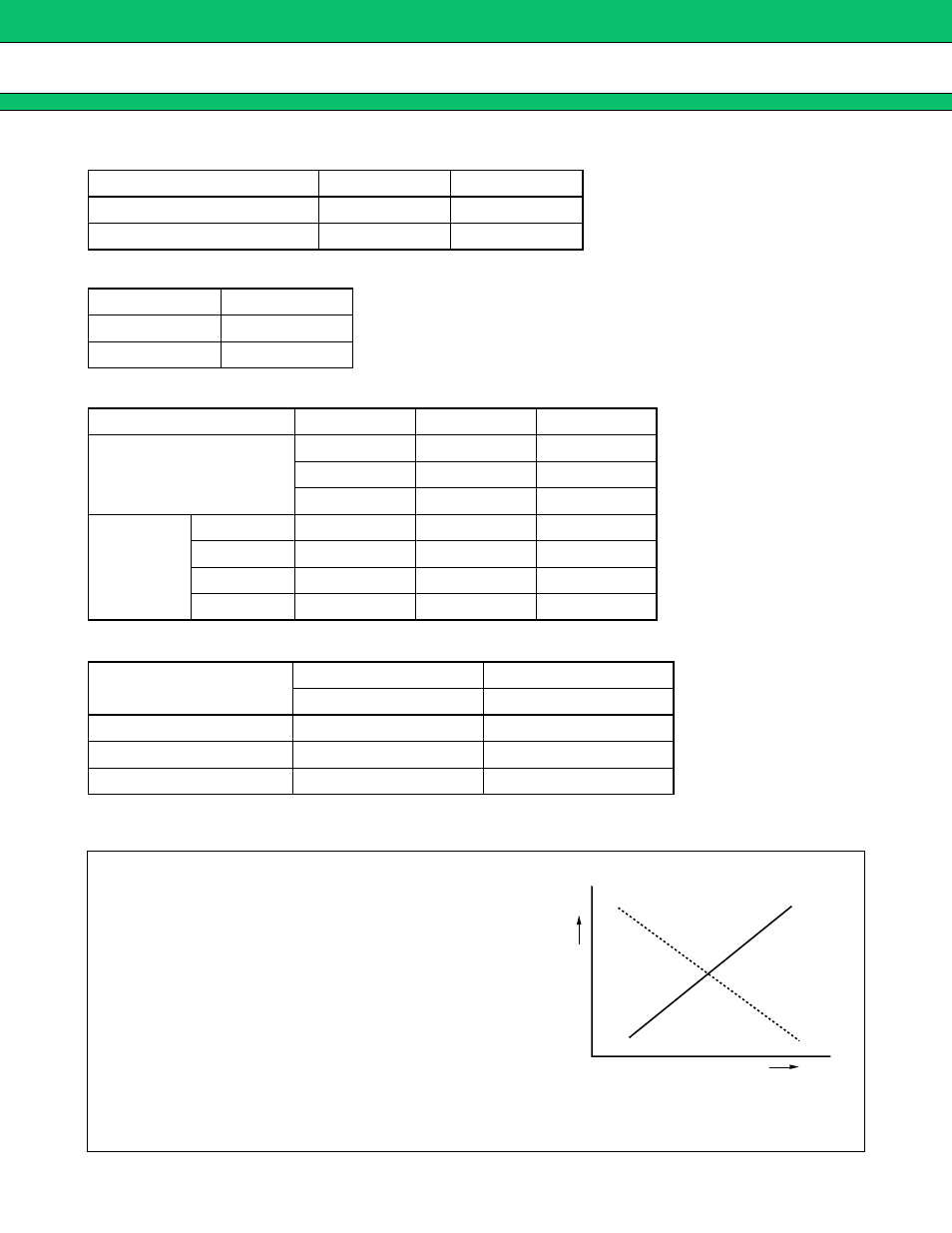
Depending upon the VCO and LPF polarity, FC bit should be set.
Divide ratio
SW
====
“H”
SW
====
“L”
Prescaler divide ratio IF-PLL
32/33
64/65
Prescaler divide ratio RF-PLL
64/65
128/129
Current value
CS
±
6.0 mA
1
±
1.5 mA
0
LD/fout pin state
LDS
T1
T2
LD output
0
0
0
0
1
0
0
1
1
fout
output
fr
IF
1
0
0
fr
RF
1
1
0
fp
IF
1
0
1
fp
RF
1
1
1
Phase comparator input
FC
IF
,
RF
====
“H”
FC
IF
,
RF
====
“L”
Do
IF
,
RF
Do
IF
,
RF
fr
>
fp
H
L
fr
<
fp
L
H
fr
=
fp
Z
Z
(1)
(2)
(1) VCO polarity FC
=
“H”
(2) VCO polarity FC
=
“L”
Note : Give attention to the polarity for using active type LPF.
VCO Output
Frequency
High
LPF Output voltage
Max