Frymaster FOOTPRINT PRO SERIES 35 User Manual
Page 15
2-5
4. Test the fryer electrical system:
a. Plug the fryer electrical cord(s) into a grounded electrical receptacle.
b. Place the power switch in the ON position.
• For fryers equipped with thermostat controls, verify that the power and heat lights are lit.
• For fryers having computer or digital displays, verify that the display indicates
c. Place the fryer power switch in the OFF position. Verify that the power and heat lights are
out, or that the display is blank.
5. Refer to the data plate on the inside of the fryer door to verify that the fryer burner is configured
for the proper type of gas before connecting the gas line quick-disconnect device or piping from
the gas supply line.
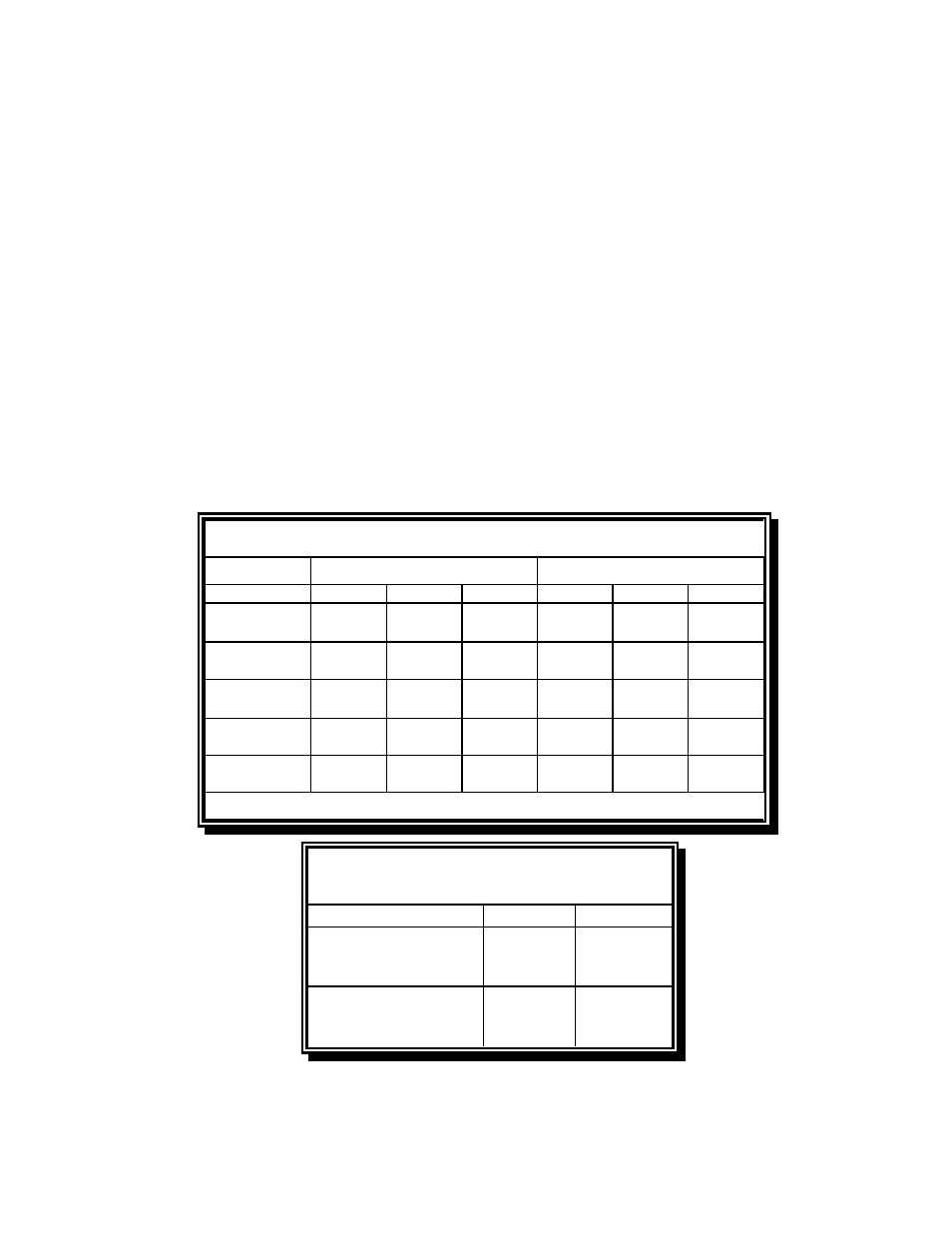
6. Verify the minimum and maximum gas supply pressures for the type of gas to be used in
accordance with the accompanying tables:
Model
Gas Type
G20
G25
G31
G20
G25
G31
Pressure
(mbar)
1
20
20-25
37-50
20
20-25
37-50
Number of
Orifices
9
9
9
18
18
18
Manifold
Pressure
9
13,5
22,5
7,5
10
20,6
1
(mbar) = 10,2 mm CE
Orifice
Size
2,50
3,06
1,51
3,10
3,58
1,80
1,40
Table 1: CE Standard for Incoming Gas Pressures
Model 35
Model 45
1,40
0,86
Air Flow
(m
3
/H)
1,70
1,70
1,05
Table 2: Non-CE Standard
for Incoming Gas Pressures
Gas
Minimum
Maximum
Natural
6" W.C.
1.49 kPa
14.93 mbar
14" W.C.
3.48 kPa
34.84 mbar
LP
11" W.C.
2.74 kPa
27.37 mbar
14" W.C.
3.48 kPa
34.84 mbar
7. For fryers equipped with a built-in filter system and/or basket lifts, plug the electrical cord(s) into
a power receptacle behind the fryer.