Frymaster GBC EN User Manual
Page 41
A-2
4
15
2
3
5
7
7
8
9
10
11
12
13
14
16
18
17
8
11
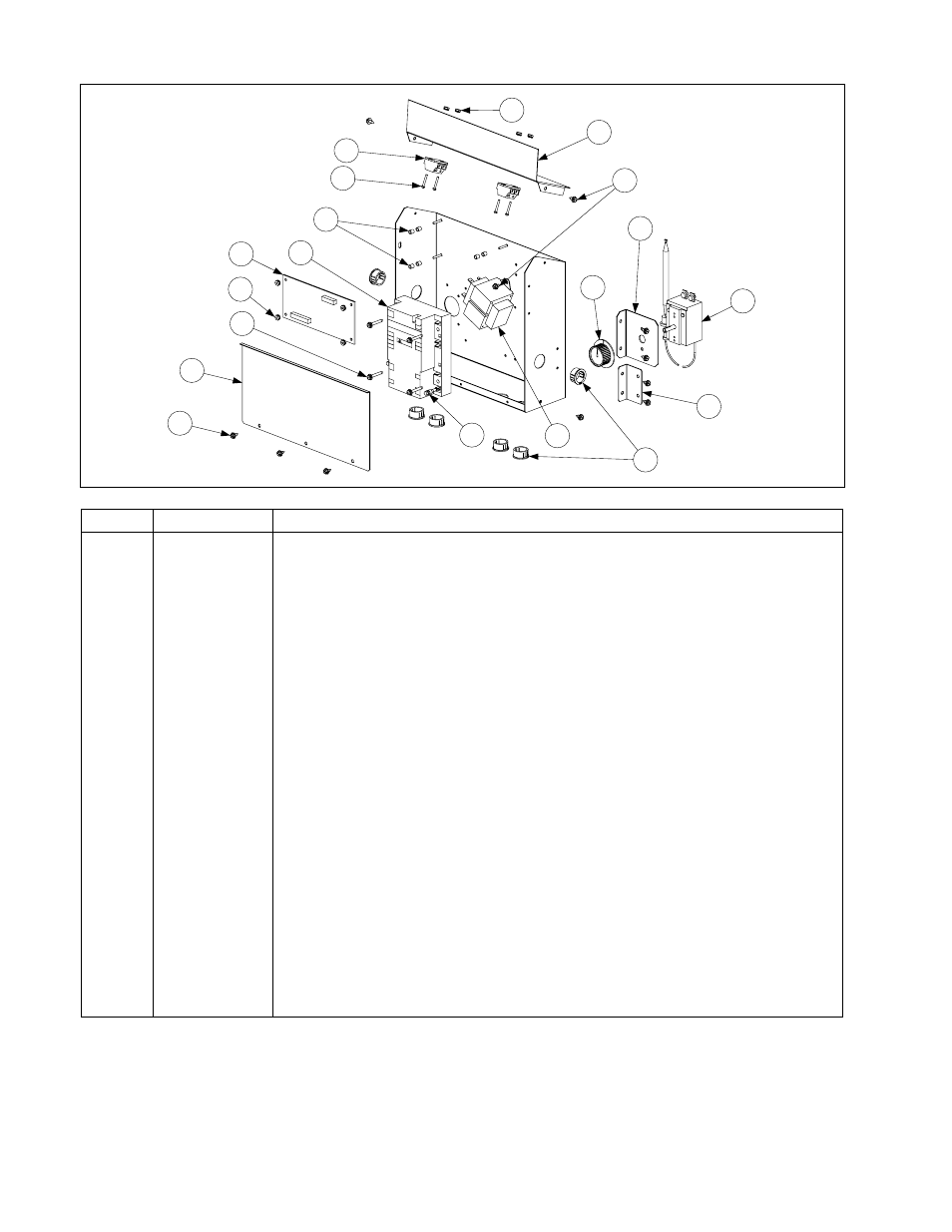
CONTROL COMPONENTS
Item Part
#
Component
1 806-8667
GSW/GWB
Control
Box
2
806-9592
Interface Board (Water Board)
3
807-0800
Transformer, 120V/24VAC 50/60 Hz, 50 VA
4 807-2272
Thermostat,
Operating
5 807-3366
Module, Dual Spark Honeywell Ignition (See NOTE below.)
6 807-3484
Connector,
Rajah
7
809-0164
Screw, #8 X 1-inch Slotted Hex Washer Head
8
826-1366
Nut, 4-40 Keps Hex (package of 25)
9
809-0349
Spacer, 4 mm X 6 mm Aluminum
10
826-1359
Screw, 4-40 X ¾-inch Round Slot Head (package of 25)
11
809-0360
Screw, #8 X ⅜-inch Slotted Hex Washer Head
12
810-0045
Bushing, .875-inch Diameter (fits 11/16-inch hole)
13
810-0387
Knob, Thermostat Control
14
810-1164
Terminal Block, 1-Piece Screwless
15
900-2484
Mount, Operating Thermostat
16
900-2769
Top Cover, Control Box
17
900-2919
Front Cover, Control Box
18
900-2958
Bracket, Control Box Mounting
*
807-2273
Switch, SPDT (Skim Feature and Faucet ON/OFF Switch)
*
807-0495
Light, Split, 24V Red and White
*
807-2479
Switch, SPDT ON/OFF Rocker (Power Switch)
* 910-2454
Panel,
Control
* Not illustrated.
NOTE: Units manufactured prior to October 2000 were equipped with two 807-1006 ignition
modules. Use a single 807-3366 module to replace them. Refer to wiring diagram 805-0521 on
Page A-6 for new wiring connections. The new modules also require the use of a new ignition cable
(P/N 106-0676).