Furuno FAR-2157 User Manual
Page 7
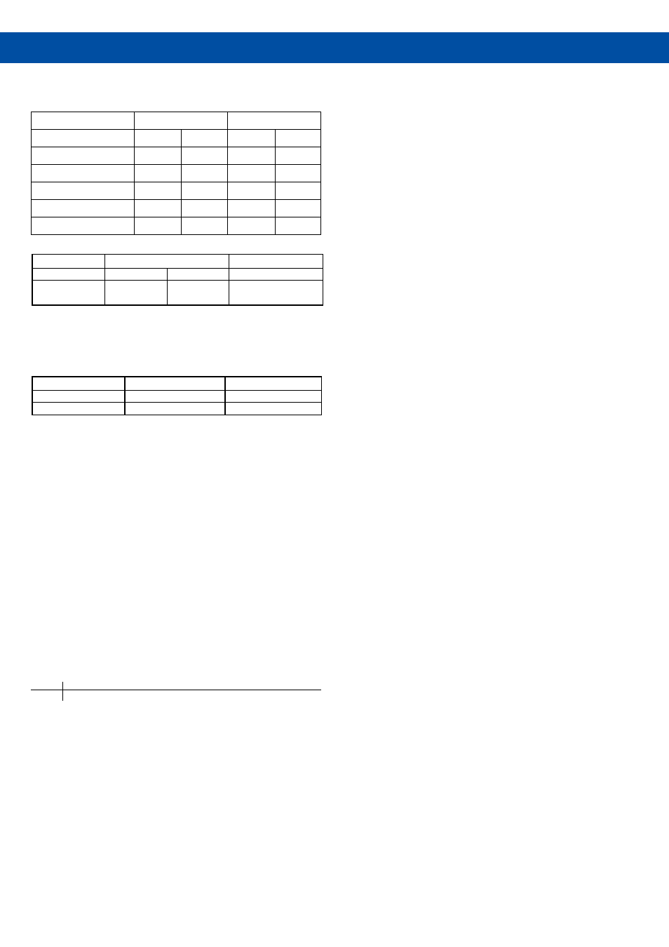
SPECIFICATIONS OF FAR-2157/2167DS
ANTENNA RADIATORS
1. Type
Slotted waveguide array
2. Beamwidth and sidelobe attenuation
X-Band
S-Band
Radiator Type
XN-4A
XN-5A
SN-30AF
SN-36AF
Length
8 ft
10 ft
10 ft
12 ft
Beamwidth (H)
0.95˚
0.75˚
2.25˚
1.8˚
Beamwidth (W)
20˚
20˚
25˚
25˚
Sidelobe (within ± 10˚)
-28 dB
-26 dB
-24 dB
-24 dB
Sidelobe (outside ± 10˚)
-32 dB
-30 dB
-30 dB
-30 dB
3. Rotation
X-Band
S-Band
Rotation
18/22 rpm
22 rpm
21/26 rpm
Gear Box
RSB-106
RSB-107
RSB-111
RSB-112
RF TRANSCEIVER
1.Frequency
X-band:
9410 MHz ± 30 MHz
S-band:
3050 MHz ± 30 MHz
2. Output power
FAR-2157
FAR-2167DS
Output Power
50 kW
60 kW
Transceiver
RTR-083
RTR-084
3. Pulselength/PRF
Range scale (nm)
Pulse length (µs)
PRF (Hz)
0.125, 0.25
0.08
1900
0.5
0.08
1900
0.75, 1.5
0.08, 0.2
1100, 1900
3
0.2, 0.6
1100, 600
6
0.2, 0.6, 1.2
1100, 600
12, 24
0.6, 1.2
600
48
1,2
600
96, 120
1.2
500
4. I.F.
60 MHz
5. Bandwidth
Short pulse
:
40 MHz
Medium pulse: 10 MHz
Long pulse:
3 MHz
RADAR DISPLAY
1. Display∗
20.1” color LCD (SXGA 1280×1024 pixels),
400 (H) × 320 (V) mm,
Effective display diameter: 308 mm
Echo Color: 12 colors (ex. red, yellow, green, blue, purple) in 24 levels
2. Range scales and ring intervals (nm)
Range .125, .25, .5, .75, 1, 1.5, 2, 3, 4, 6, 8, 12, 16, 24, 32, 48, 96, 120
Ring .025, .05, .1, .25, .25, .25, .5, .5, 1, 1, 2, 2, 4, 4, 8, 8, 16, 20
3.
Minimum range
30 m on 0.75 nm range scale
4. Range discrimination
30 m on 0.75 nm range scale
5. Range ring accuracy
Within ± 1 %
6. Presentation modes
Head-Up, Course-Up, North-Up, North-Up True Motion
7. Parallel index lines
1, 2, 4 or 6 lines (selectable in menu)
8. Radar map
20,000 points to create coastlines, own ship safety contour, marks, com-
ments, isolated underwater dangers, buoys, traffic routing systems, prohib-
ited areas, fairways.
AUTOMATIC PLOTTING
1. Acquisition
100 targets (e.g. manually 50, automatically 50)
2. Tracking
Automatic tracking of all acquired targets in 0.1 to 32 nm
3. Guard zone
Two zones, one of them 0.5 nm depth
4. Vector
True or relative 30 s, 1-15, 20, 30 min for prediction of target motion
5. Past positions
5 or 10 past positions at intervals of 30 s,1, 2, 3, 6 min.
6. Collision warning
CPA limit: 0.2 - 10 nm, TCPA limit: 0 - 99 min.
7. Trial maneuver
Dynamic or static, with selected delay time.
AIS DISPLAY
1. Symbols
Sleeping, Activated, Dangerous, Selected, Lost targets
2. Number of targets
1,000 targets max.
3. Data indication
Basic and expanded data
POWER SUPPLY (specify when ordering)
1. Processor Unit
100-115/220-230 VAC, 1ø, 50/60 Hz
3.0 A (100-115 VAC)
1.5 A (200-230 VAC)
440 VAC, 1ø, 50/60 Hz with optional transformer RU-1803
2. Monitor Unit
∗
100-230 VAC, 1ø, 50/60 Hz
440 VAC, 1ø, 50/60 Hz with optional transformer RU-1803
3. Antenna Unit
FAR-2157:
24 VDC
200 VAC, 3ø, 50 Hz; 220 VAC, 3ø, 60 Hz
100-115/220-230 VAC, 1ø, 50/60 Hz with optional transformer RU-3423
110 VAC, 3ø, 60 Hz with optional transformer RU-5693
220 VAC, 3ø, 50 Hz with optional transformer RU-6522
440 VAC, 3ø, 50 Hz with optional transformer RU-5466-1
FAR-2167DS:
200 VAC, 3ø, 50 Hz; 220 VAC, 3ø, 60 Hz
380 VAC, 3ø, 50 Hz; 440 VAC, 3ø, 60 Hz
110 VAC, 3ø, 60 Hz with optional transformer RU-5693
220 VAC, 3ø, 50 Hz with optional transformer RU-6522
440 VAC, 3ø, 50 Hz with optional transformer RU-5466-1
STANDARD
1. Monitor Unit MU-201CR∗
2. Processor Unit RPU-013
3. Standard type Control Unit RCU-014
Trackball type Control Unit RCU-015
(Specify when ordering)
4. Antenna Unit with cable, 15/30/40/50 m (Specify when ordering)
5. Power Supply Unit PSU-006
6. Standard Spare Parts and Installation Materials
OPTION
1. Remote Control Unit RCU-016
2. Gyro Converter GC-10-2 (built in Processor Unit)
3. DVI-RGB Converter Kit (Buffer board built in) OP03-180-2
4. BNC Connector Converter DSUB-BNC-1 (for VDR)
5. Chart/Memory Card Interface Unit CU-200
6. Stepdown Transformer Unit RU-1803/5466-1/5693/6522
7. Rectifier Unit RU-3423
8. Antenna Cable RW-9600
9. External Alarm Buzzer OP03-21
10. Hand Grip Assembly FP03-09840
11. Bracket Assembly FP03-09820
12. Switching Hub HUB-100
∗ BlackBox types do not include monitor unit.