Rear panel – Furman Sound PS-PRO II User Manual
Page 7
P S - P R O I I - P O W E R C O N D I T I O N E R / S E q u E N C E R
BNC Connector
for rear light
(models GN-I or
GN-LED)
POWER STaTuS (DElaY) lEDs: One green
LED is provided for each of the three delay
stages. Each LED lights when power is applied
to its corresponding duplex outlet on the rear
panel. All three LEDs then remain lit until power
is removed. During the power-down delay cycle,
each LED goes off as power to its correspond-
ing outlet is removed. In addition, the Delay 1
LED flashes if a remote switch (or the stored
state) is OFF.
uNSWITCHED OuTlET: This convenient outlet
provides power at all times when the PS-PRO II
is plugged in and operating under normal power
conditions.
CIRCuIT BREaKER: The overall capacity of
the PS-PRO II is 20 amps. Should the com-
bined steady-state current drawn by all devices
plugged into the unit at any time exceed 20
amps, the circuit breaker will trip, cutting off
power to your rack. If this occurs, reduce the
load by unplugging one or more units from the
PS-PRO II, and reset it. you can reset the circuit
breaker by simply pressing the button, which
pops out when tripped. However, because it
is a thermal type, you may have to wait a few
moments after it trips for it to cool down before
it will allow you to reset it.
ON/REm/OFF SWITCH: When turned to the
ON position, this key lock switch initiates an
ON sequence, applying power to the PS-PRO
II’s switched outlets. When turned to the OFF
position, it begins an OFF sequence. In the
REM position, the PS-PRO II will accept on/off
commands from a remote switch or switches that
may be connected to the rear panel terminals.
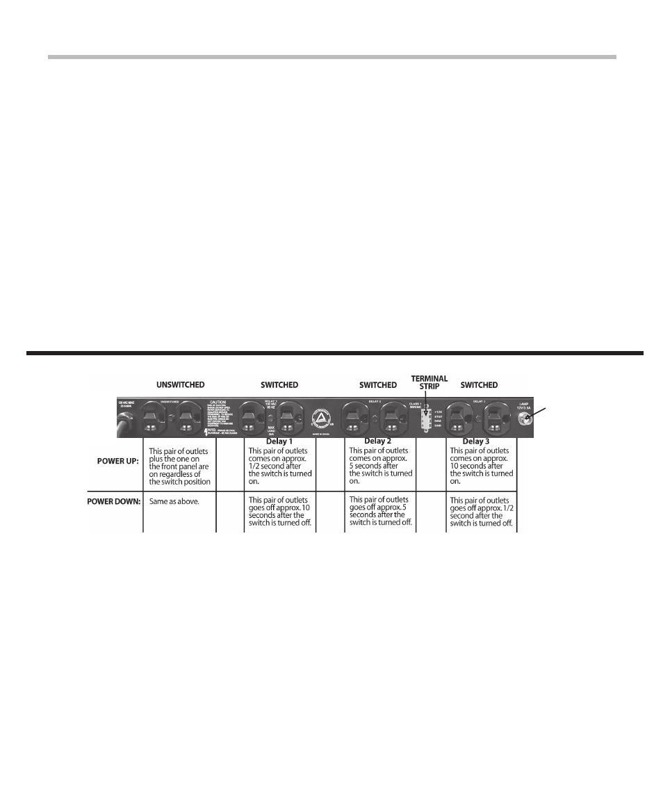
UNSWITCHED OUTLETS: The PS-PRO II rear
panel provides clean, filtered power to this pair
of unswitched outlets, adjacent to the power
cord.
SWITCHED (DELAyED) OUTLETS: The
PS-PRO II rear panel provides three pairs of
switched outlets, widely spaced to allow use of
equipment with plug- in (wall wart) transformers.
These switched outlet pairs are labeled Delay 1,
Delay 2 and Delay 3. After the front panel switch
is thrown to ON, Delay 1 outlets receive power
instantly, Delay 2 outlets receive power 1-30
seconds later and Delay 3 outlets receive power
1-30 seconds after Delay 2 outlets are powered.
When thrown to OFF, the sequence is reversed,
with Delay 3 losing power instantly, Delay 2 out-
lets losing power 1-30 seconds later and Delay
1 outlets losing power 1-30 seconds after Delay
2 outlets are shut down. The delay intervals
may be altered with the screwdriver-adjustable
Delay Adjust control on the front panel.
TERMINAL STRIP: Allows one or more switches
to be connected to turn the PS-PRO II on and
off from a remote location. Two, and sometimes
three, wires are needed to install a remote
switch (see “Maintained Mode”, page 6.) If a
four-conductor cable is used, an LED may be
installed at the remote end to indicate that the
power is on.
REaR PaNEl
6