Installation – FMI ES401 User Manual
Page 6
www.fmiproducts.com
122638-01E
6
Note: It is strongly advised that you hire
a qualified professional to undertake this
step in order to prevent personal injury.
Once flue is capped, chimney is no longer
suitable for wood burning.
Note: Do not install this unit into a fireplace
that is prone to dampness, the area of
installation must be dry.
4. Plan the power supply. Unit does not come
with a power cord. Unit must be hard wired
to either a 120/60 or 240/60 volt supply.
WARNING: The solid fuel/gas
fireplace has been converted for
use with an electric insert and
cannot be used for original fuels
unless all original parts have
been replaced and the fireplace
has been reapproved by the au-
thority having jurisdiction.
New Construction or Renovation
1. Select a location at least 3 feet (0.9 m)
away from combustible materials such
as curtains or drapes, furniture, bedding,
paper, etc.
2. Mark desired location on floor and store
unit in a safe, dry and dust free location.
3. Frame in an opening leaving at least 1/4"
(6 mm) around the edge of the unit (see
Framing). Any new wiring must be done in
compliance with local and national codes
and other applicable regulations in order
to reduce the risk of fire, electric shock
or other injuries. Therefore, it strongly
recommended that you hire a professional
to complete any such work.
4. Plan your power supply route. See step 4
of Existing Fireplace Installation, above.
Built-In Fireplace
1. Remove front panel and front glass from
fireplace (see Cleaning and Maintenance,
page 8).
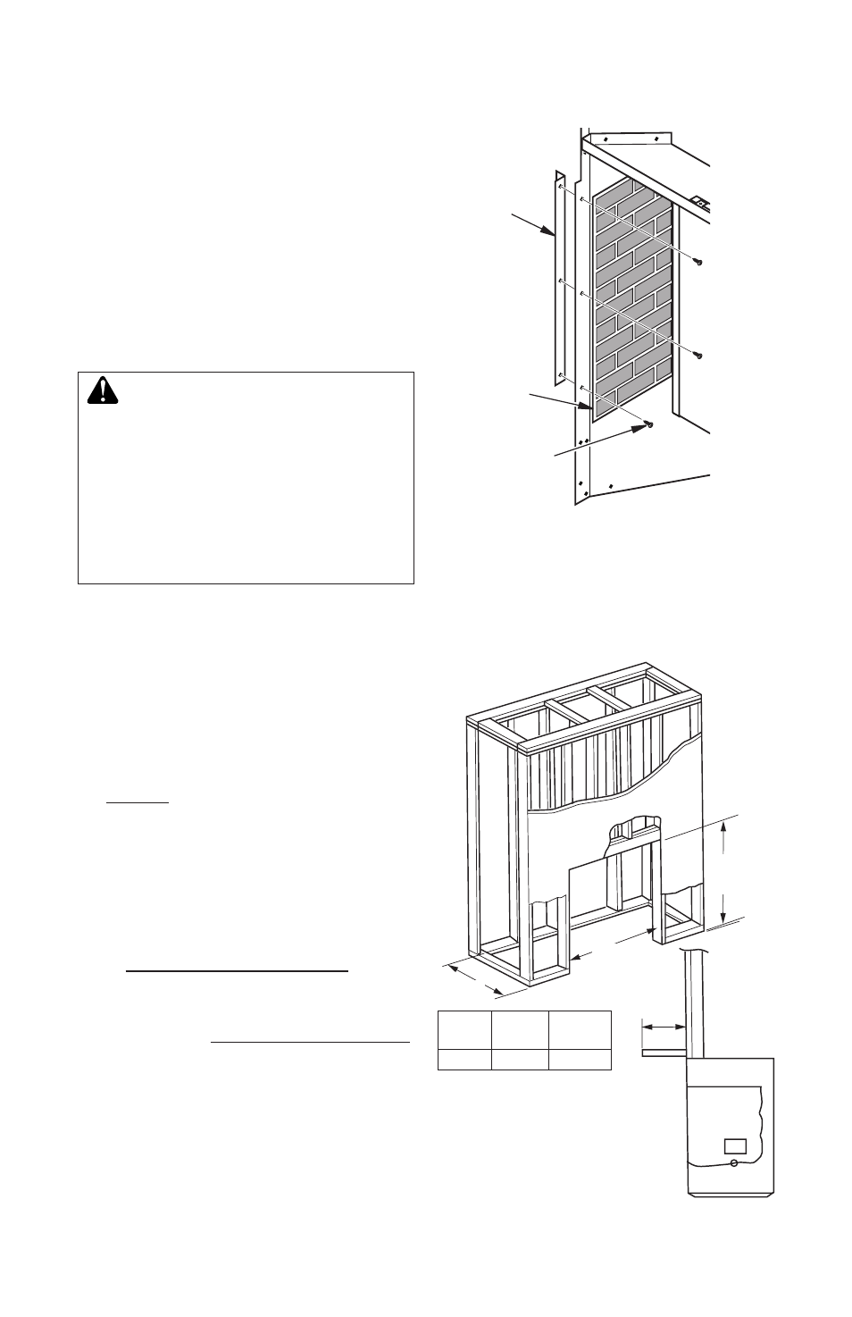
2. Locate 3 prepunched clearance holes
in each side of fireplace. Press screws
through brick liner, then attach nailing
flange brackets to each side of fireplace
(see Figure 4).
Framing
Figure 5, shows a typical framing of this heater
using combustible materials. All required
clearances to combustibles must be adhered
to. Header height is measured from the base
of the heater.
INSTALLATIoN
Continued
Figure 5 - Framing Heater for New
Construction/Renovation
Length
Header
Height
Depth
0.75"-
0.50"
Depth Length Header
Height
10.5"
34"
32"
Note: The height that a
combustible mantel is fitted
above the heater is a minimum
of 1" above the front.
Figure 4 - Attaching Nailing Flange Brackets
Nailing
Flange
Bracket
Brick
Liner
Screw