Mb3773 – FUJITSU MB3773 User Manual
Page 24
MB3773
24
C
R
T
1
0.01
µ
F
10 k
Ω
30
µ
s
0.1
µ
F
10 k
Ω
300
µ
s
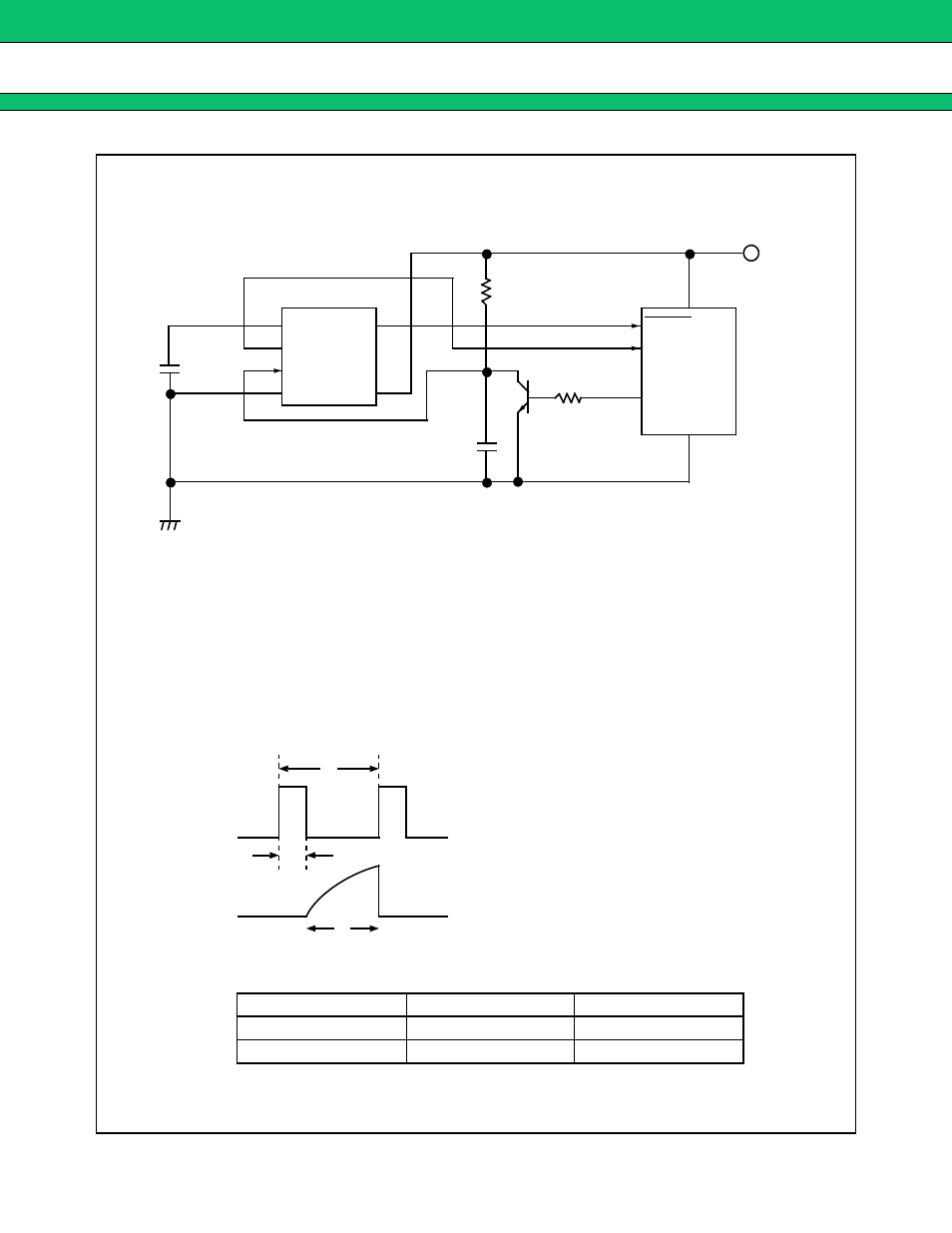
EXAMPLE 11: Circuit for Limiting Upper Clock Input Frequency
Notes :
•
This is an example application to limit upper frequency f
H
of clock pulses sent from
the microprocessor.
If the CK cycle sent from the microprocessor exceeds f
H
, the circuit generates a reset signal.
(The lower frequency has already been set using C
T
.)
•
When a clock pulse such as shown below is sent to terminal CK, a short T
2
prevents C
2
voltage
from reaching the CK input threshold level ( := 1.25 V), and will cause a reset signal to be output.
The T
1
value can be found using the following formula :
Example : Setting C and R allow the upper
T
1
value to be set (See the table below).
V
CC
(5 V)
1
2
3
4
8
7
6
5
C
T
RESET
RESET
CK
GND
R
2
R
1
=10 k
Ω
C
2
T
r1
T
1
:= 0.3 C
2
R
2
T
2
CK waveform
T
3
C
2
voltage
T
1
where V
CC
=
5 V, T
3
≥
3.0
µ
s, T
2
≥
20
µ
s