Install ductwork, Install electrical wiring, Wiring diagram install cooktop – FRIGIDAIRE HV2730B User Manual
Page 4: Adjustment
INSTALL DUCTWORK
CAUTION -
BEFORE CUTTING HOLE IN CABINET FOR DUCT-
WORK: Check for interference with floor joists, wall studs,
electrical wiring or plumbing.
1. Cut hole in cabinet as well as holes in wall or floor as
necessary.
2. Mount the roof or wall cap and work back towards the cabinet,
attaching all ductwork, elbows and transitions as previously
planned. Tape all ductwork connections to make them secure
and air tight.
3. Connect ductwork (and transition, if required) to downdraft. If
necessary, LOOSEN nuts and screws that hold the blower in
place, and slide blower left or right to meet ductwork. Re-
tighten screws and nuts.
Note: A 3-1/4" x 10" collar is provided for installers who prefer to
rivet the ductwork to the unit. This will allow blower to be removed
and replaced easily in service situations without disturbing
ductwork.
INSTALL ELECTRICAL WIRING
1. Mount a standard wiring box, with 3-pronged receptacle,
inside the cabinet. Make sure the downdraft’s power cord can
easily reach it.
2. Run appropriate power cable into cabinet and connect it to
receptacle.
3. Plug the downdraft’s power cord into the outlet.
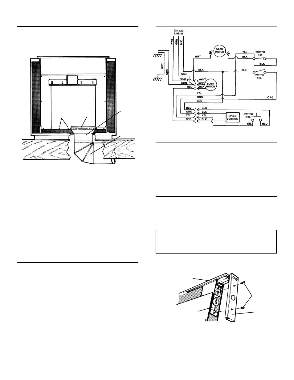
WIRING DIAGRAM
INSTALL COOKTOP
1. Align the cooktop with the downdraft and fasten cooktop in
place.
Note: Accurate alignment of cooktop and downdraft is necessary
to ensure that there is no interference when air vent is raised and
lowered. There should be a gap of 1/32"-1/16" between the back
of the cooktop and the front of the downdraft cover.
ADJUSTMENT
The downdraft is factory-adjusted for proper operation. How-
ever, shipping and handling may affect the position of the
activating switch.
To adjust position of activating switch:
WARNING: To avoid possible electrical
shock, personal injury or death -
Disconnect electrical power.
1. If downdraft is plugged into electrical outlet, unplug it.
2. Lift air vent straight up and cock it slightly so it remains in the
UP position.
6" RD.
ELBOW &
DUCTWORK
3-1/4" X 10"
TO 6" RD.
TRANSITION
ç
BLOWER
è
COLLAR
SCREWS
3. Remove switch cover from right end of air vent.
4. Loosen the 2 screws holding the switch bracket in place.
Position switch bracket so that activating switch just comes in
contact with underside of switch membrane. Tighten screws.
5. Replace switch cover, gently lower air vent into chimney, and
plug in power cord. Re-connect electrical power and check
operation.
SWITCH
COVER
SCREWS
SWITCH
MEMBRANE
SWITCH
BRACKET
4