Table 2-4. 977-200-15m test points, Table 2-5. 977-210-10m leds, Table 2-6. 977-210-10m test points – Fluke 943-227-15 User Manual
Page 16
943-227-15 Digital Preamplifier
Operator Manual
2-4
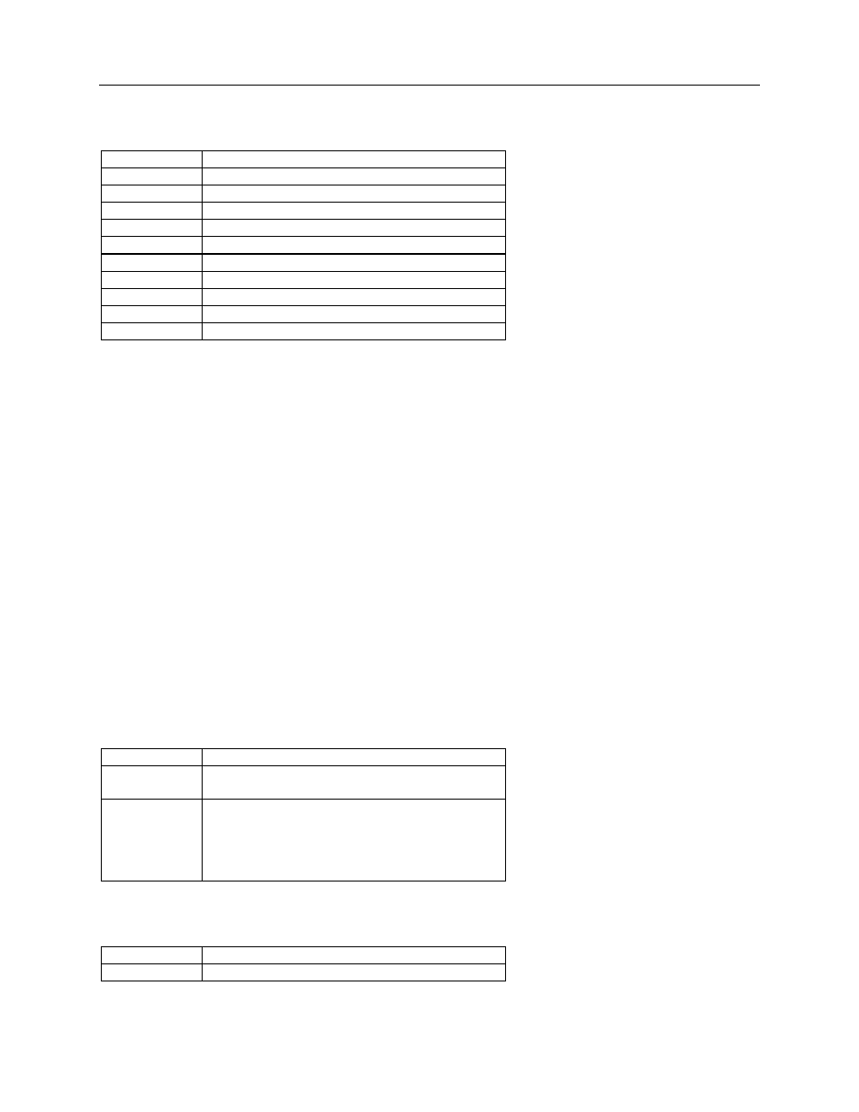
The following Test are provided on the 977-200-15M board:
Table 2-4. 977-200-15M Test Points
Test Point
Function
TP1 Electrometer
Output
TP2
Analog +5 VDC supply
TP3
- 5 VDC supply
TP4
Digital +5 VDC supply (From 977-210-10M)
TP5
High Voltage Sense (Not Used)
TP6
+ 12 VDC supply (From 977-210-10M)
TP7 DC
Ground
TP8
Programmable Gain Amplifier Output
TP9
Microprocessor Clock Signal
TP10
Chip Enable - EPROM
2.4 977-210-10M Interface Board
Refer to the Communications Interface, P/N 977-210-13M, schematic diagram in Appendix B. U12 is an
asynchronous communications interface adapter (ACIA) which communicates with the UDR or 960
system. U1 is an analog switch used to select either the
Victoreen loop or the RS232 driver/receiver for
external communications. Optical isolation U10 isolates data transmitted on the
Victoreen loop while the
circuitry comprised of Q6, Q7, Q14, and Q18 are the actual loop drivers. Optical isolator U8 isolates the
receive data from the Victoreen loop.
U2 and U3 are, respectively, the receiver and driver circuits for the RS232 port. U14 decodes address
block A000 to provide chip enables to the ACIA switch input register U6.
Regulated power for the electronics (+/- 12 VDC) is derived from three terminal regulators VR3 and VR4.
The ±5 Vdc logic power is derived from the three terminal regulators VR1 and VR2.
Power for the detector is normally provided by the electronic high voltage power supply in the associated
Model 942A-200C UDR or Model 960 System.
The following LEDs are provided to indicate operation of certain functions of the 977-210-10M board:
Table 2-5. 977-210-10M LEDs
LED #
Indicates
LED1
+15 VDC is being supplied to the circuit board
from the UDR when ON
LED2
Communications – Receive;
ON (bright): both + 15 and -15 volt loops
present
ON (dim): Only one loop supply present
OFF: no loop voltage from either supply
The following Test are provided on the 977-210-10M board:
Table 2-6. 977-210-10M Test points
Test Point
Function
TP2 RS232
Transmit