Fluke 943-227-15 User Manual
Page 29
943-227-15 Digital Preamplifier
Operator Manual
A-2
A.2 SWITCH AND JUMPER POSITIONS,
943-227-15 and 943-227-15VL
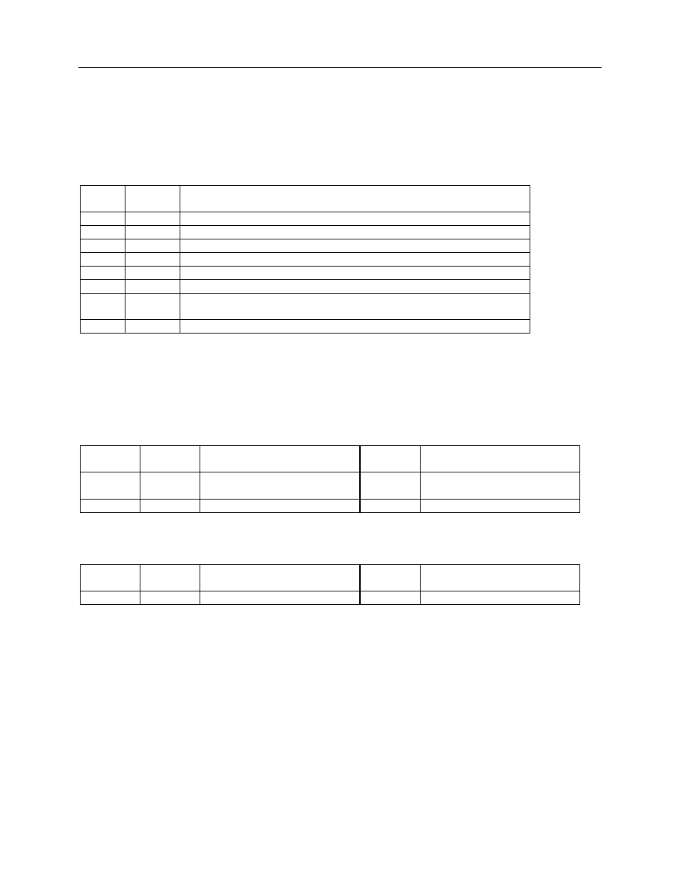
Table A-2. Preamplifier Serial Interface Board 977-210-10M Switch Settings
Switch Normal
Op.
Switch Function
SW1
Open
Microprocessor Reset switch, momentary contact
SW2
N/A
Not supplied
SW3-1
ON
OFF Selects 300 baud • 1/ON Selects 4800 baud (normal setting)
SW3-2
OFF
OFF • (No function is implemented in the 977-210-10M)
SW3-3
OFF
OFF Selects Rate Mode (normal) • (Selects Maintenance Mode for
factory PGA and Auto Zero set-up only)
SW3-4
OFF
OFF • (No function is implemented in the 977-210-10M)
NOTE
SW3 is a 4-position DIP switch on the 977-210-10M serial
interface board.
Table A-3. Jumper Positions for Preamplifier Serial Interface Board 977-210-10M
Jumper Normal
Setting
Function Alternate
Setting
Function
JMP1
A to B
Enables
Victoreen Loop
(normal)
B to C
Enables RS232C
JMP2
N/A
Deleted, Not Used
N/A
Deleted, Not Used
Table A-4. Jumper Positions for Preamplifier Electrometer Board 977-200-15M
Jumper Normal
Setting
Function Cal.
Position
Function
JMP1
A to B
Normal Operation
B to C
PGA Offset Adjust *
* Programmable Gain Amplifier requires a special test PROM and is a factory adjustment