Through-the-wall installations, Before after, Top view – Friedrich KM24 User Manual
Page 15
15
920-198-00
STEP 1 Follow steps 1, 2, 3 and 4 of the "STANDARD SASH WINDOW
INSTALLATION" instructions beginning on page 10.
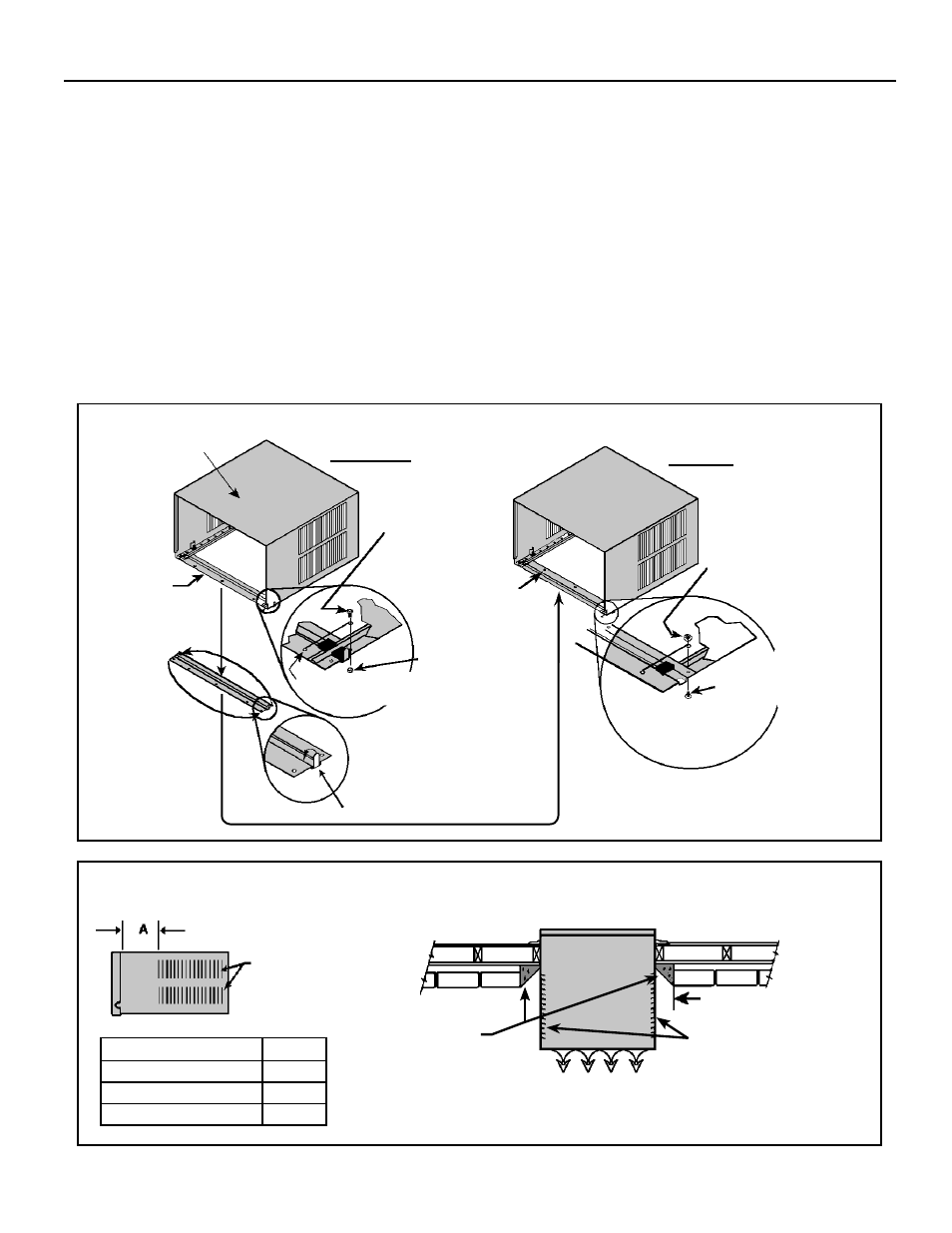
STEP 2 CABINET PREPARATION – Remove the sill plate from the
cabinet by removing the two nuts and screws retaining the sill
plate. Note that the chassis retainer is secured by a right side
nut and screw (See Detail 1, Figure A.) Bend the tabs of the
sill plate down into its channel at both ends of the plate or cut
them off (See Detail 2, Figure A.) Turn the sill plate end to end,
180° and reinstall. Reverse the orientation of nuts and screws
so that the head of screw is on bottom of cabinet facing up and
nut is on top facing down (See Detail 3, Figure A.) Insure that
the chassis retainer is reinstalled as shown in the detail.
Figure A
BEFORE
AFTER
CABINET
SILL
PLATE
TURN SILL PLATE
END TO END
SCREW
(2 REQUIRED)
NOTE: HOLES
MOVED TO
BACK SIDE
NUT
(2 REQUIRED)
RETAINER, CHASSIS
THIS SIDE ONLY
DETAIL 1
BEND TABS DOWN
DETAIL 2
DETAIL 3
SCREW
(2 REQUIRED)
SCREW AND NUT
ORIENTATION NOW
REVERSED
NUT
(2 REQUIRED)
STEP 3 WALL PREPARATION – The maximum wall thickness permis-
sible without special construction is determined by the model size
to be installed. THE OUTSIDE CABINET CONDENSER-AIR-
INTAKE-LOUVERS MUST NOT BE BLOCKED BY EXTENDING
INSIDE THE WALL AREA. Observe the maximum wall thickness
shown in the chart and diagram in Figure B.
SPECIAL INSTRUCTIONS FOR EXTRA THICK WALLS –
For installation in walls exceeding the maximum thickness shown
in the chart, the following suggested construction may apply.
2" MINIMUM
BOTH SIDES
CONDENSER AIR
INTAKE LOUVERS
MAXIMUM WALL THICKNESS
CONDENSER
AIR INTAKE
LOUVERS
TOP VIEW SHOWING
BEVELED SIDES FOR
AIR INTAKE. WALL
BELOW UNIT MUST BE
BEVELED ALSO.
TOP VIEW
CONDITIONED ROOM SIDE AIR
CONDENSER AIR
OUTLET / REJECTED
HEATED AIR
NOTE: Condenser air inlets
and outlet must be unobstruct-
ed to avoid the recirculation of
rejected heated air.
MODEL
A
SMALL CHASSIS
7 ⅜"
MEDIUM CHASSIS
7 ⅜"
LARGE CHASSIS
15 ⅛"
Through-the-wall Installations
The following instructions apply to wood, masonry, brick, concrete or cinder block wall construction
Figure B EXTRA THICK WALL CONSTRUCTION