Hardware connections, Hardware connection tips / hints – FieldServer FS-8700-124 User Manual
Page 5
ProtoNode Driver Manual (FS-8700-124) rev 6.doc Manual
Page 5 of 17
ProtoCessor 1991 Tarob Court Milpitas, California 95035 USA Web:www.protocessor.com
Tel: 408.964.4433 Fax: 408.964.4425 Toll_Free: 800.317.8319 email: [email protected]
3.
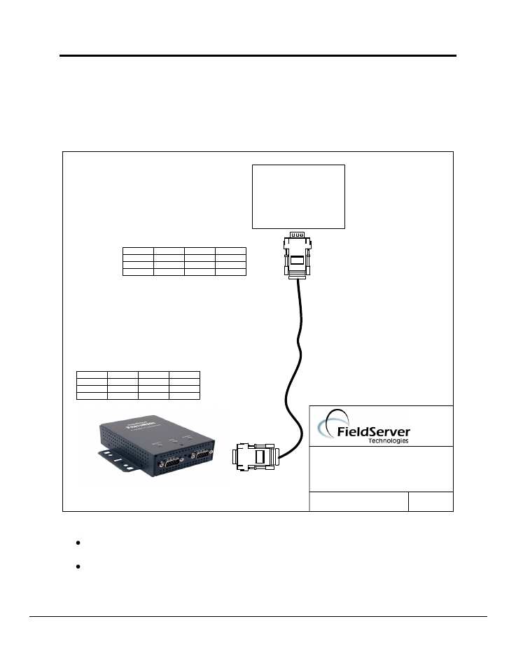
Hardware Connections
The ProtoNode is connected to the UPS as shown in connection drawing.
Configure the TIC UPS according to manufacturer’s instructions.
FUNCTION
FROM
TO
COLOUR
Rx
RJ45-01
DB9F-03
WHITE
GND
RJ45-04
DB9F-05
GREEN
Tx
RJ45-08
DB9F-02
BLUE
BASE NAME:
FILE NAME: FS-8700-124
PROTONODE
TOSHIBA UPS
CONNECTION DIAGRAM
DATE: 10/10/07
BY: MC
(408)-262-2299
8917-02 WIRE LIST
Toshiba UPS
D
B
9M
DB9F
FUNCTION
FROM
TO
COLOUR
Rx
RJ45-01
DB9M-02
GREY
GND
RJ45-04
DB9M-05
GREEN
Tx
RJ45-08
DB9M-03
BLUE
8917-03 WIRE LIST
PROTONODE
3.1.
Hardware Connection Tips / Hints
The RTS/DTS signals are not used by the driver. Make sure they are not connected and
do not enable them in the configuration file.
The cable must be a NULL modem cable, i.e. the TX must be connected to the other
connector’s RX.