Field Controls Power Venter System PVU-300 User Manual
Page 8
Page 8
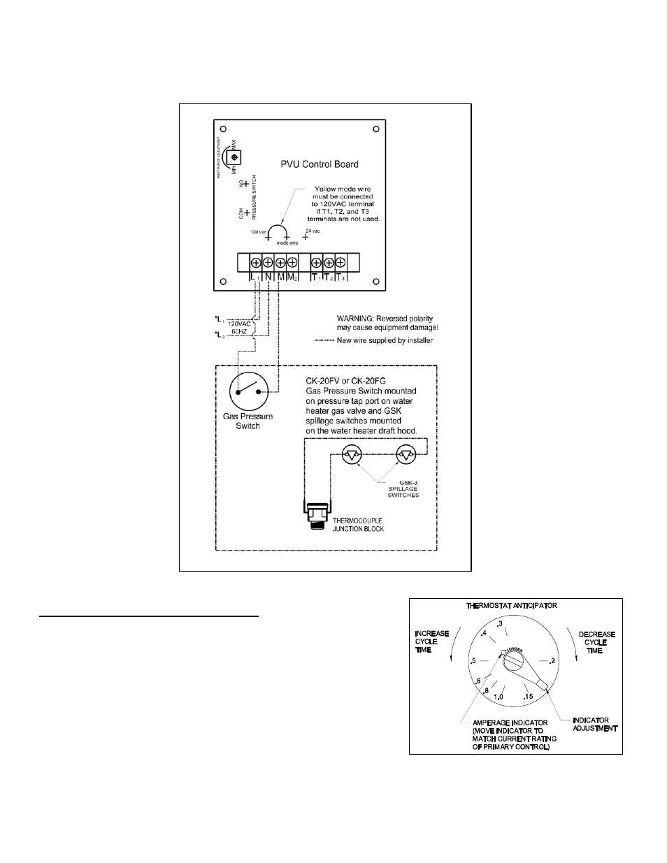
Diagram E – Wiring with a 30mV Water Heater
NOTE: A CK-20FV or CK-20FG control kit MUST be added to the system to properly control the venter with the operation
of a 30mV water heater. Refer to Diagram E for proper wiring specifications.
ADJUSTING THERMOSTAT ANTICIPATOR
If connecting the Power Venter system to a gas appliance with a
thermostat anticipator, refer to the following to make adjustments.
Disconnect one side of the thermostat circuit at the gas valve or burner
control, and connect an ampere meter into the circuit. With the system
running, take an amperage reading on the circuit. Check the nameplate or
instructions for the thermostat to obtain the proper amperage level. Adjust
amperage level by moving the anticipator lever. Reconnect the thermostat
to the gas valve and start the system operating. Time the burn cycles and
adjust as follows; To make the cycle time longer, increase the amount on
the anticipator (Example: .45 to .5 Amps); to decrease cycle time, reduce
the amount on the anticipator. (Example: .45 to .3 Amps) (See Figure 8)
Figure 8