Field Controls Power Venter System PVU-300 User Manual
Page 11
Page 11
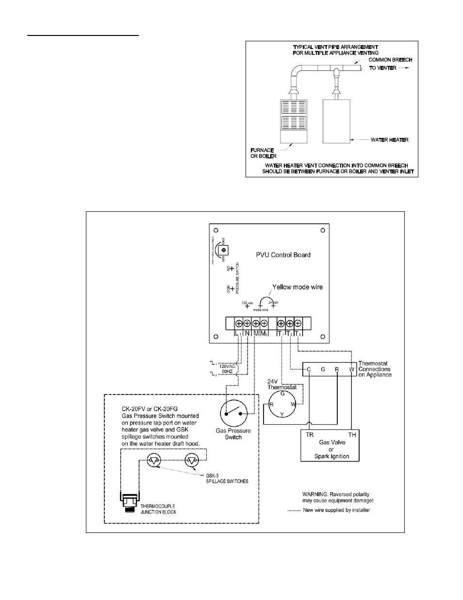
Diagram F – Multiple Wiring with 24 VAC Furnace and 30mV Water Heater
MULTIPLE VENTING SYSTEMS
1. To vent a 24 VAC controlled boiler or furnace and a 30
millivolt residential water heater using one PVU power
venter refer to the following.
a. Follow the instructions for safe and proper venting
previously specified in this manual. Make sure that the
combined gross BTU/Hr input and equivalent vent pipe
length does not exceed the maximum venting capacity
of the venter selected.
b. A CK-20FV or CK-20FG control kit MUST be added to
the system to properly control the venter during
operation of the water heater. Refer to Figure 10 and
Diagram F for vent pipe arrangement and wiring
information.
Figure 10