FUJITSU FCN-087 User Manual
Page 5
5
Fcn-086 / 087 series
Dimensions are in millimeters (inches)
www.fcai.fujitsu.com
Specifications
subject to change
n
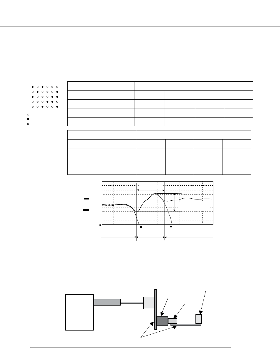
transmission characteristics
The transmission characteristics were designed to an optimum level by repeating various transmission
characteristics simulations when the structure was designed, so as to improve the transmission character-
istics of this connector. The characteristic impedance and the measurement device of the connector are
shown below.
Measurement Point
Measurement Result
1.Measurement voltage: Vin = 5.0V
2.Rise time: Tr = 100ps, 300ps, 500ps, 1ns
3.Measurement device: TDR measurement device CSA803 and SD24 (Tektronix)
4.Measurement system
Delay Time
Characteristic
Impedance
PC board part PC board part PC board part
300.0m
10.00m
V/Div.
200.0m
49.00n
100.0p S/Div
50.00n
in
out
signal
a
b
c
d
e
Not connected
Ground
Measurement signal
CSA 80.3
SD 24
Coaxial
cable for measurement
Plug
M easurement
board
50Ω termination
connecto
Socket
s
t
n
e
n
o
p
m
o
C
u
s
ti
j
u
F
tr
a
t
S
t
A
s
p
0
0
1
s
p
0
0
3
s
p
0
0
5
s
n
1
z
H
:
y
c
n
e
u
q
e
r
F
z
H
G
5
7
.
1
z
H
M
0
8
5
z
H
M
0
5
3
z
H
M
5
7
1
)
(
e
c
n
a
d
e
p
m
I
c
it
s
ir
e
t
c
a
r
a
h
C
0
.
4
6
o
t
3
.
5
4
8
.
6
5
o
t
2
.
8
4
6
.
4
5
o
t
2
.
9
4
8
.
2
5
o
t
3
.
9
4
%
:
k
l
a
t
s
s
o
r
c
d
n
e
r
a
F
/r
a
e
N
4
1
.
1
/
6
9
.
1
8
7
.
0
/
9
4
.
1
1
5
.
0
/
6
0
.
1
7
2
.
0
/
1
7
.
0
r
e
il
p
p
u
S
r
e
h
t
O
tr
a
t
S
t
A
s
p
0
0
1
s
p
0
0
3
s
p
0
0
5
s
n
1
z
H
:
y
c
n
e
u
q
e
r
F
z
H
G
5
7
.
1
z
H
M
0
8
5
z
H
M
0
5
3
z
H
M
5
7
1
)
(
e
c
n
a
d
e
p
m
I
c
it
s
ir
e
t
c
a
r
a
h
C
1
.
6
6
o
t
4
.
7
4
8
.
6
5
o
t
2
.
8
4
2
.
9
5
o
t
5
.
9
4
5
.
3
5
o
t
7
.
7
4
%
:
k
l
a
t
s
s
o
r
c
d
n
e
r
a
F
/r
a
e
N
1
4
.
1
/
4
2
.
2
8
9
.
0
/
7
5
.
1
7
6
.
0
/
4
1
.
1
5
3
.
0
/
8
7
.
0
Ω
Ω
Ω