Frymaster GF14 User Manual
Page 11
1-7
13. Remove the manometer or pressure gauge fitting from the pressure tap hole and reinstall the pipe
plug.
14. Place the gas valve in the PILOT position and check for gas leaks. If no leaks are found, re-light
the pilot and return the unit to operation.
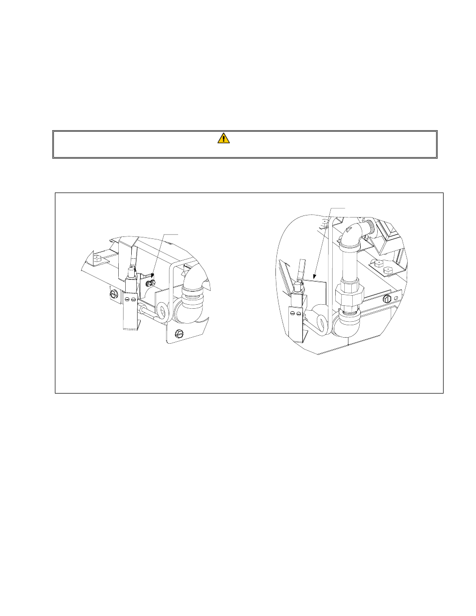
1.7.5 Replacing the Thermopile or Pilot Assembly
DANGER
Drain the frypot or remove the handle from the drain valve before proceeding further.
A pair of small screws (see illustration below) attaches the pilot assembly, which consists of the
pilot and the thermopile, to the burner manifold.
1. To replace only the thermopile, disconnect the leads from the gas valve, remove the guard, bend
the clip at the bottom of the pilot assembly outward, and press the thermopile out of the
assembly from the top. Reverse the procedure to install the replacement thermopile.
On GF40 units,
the pilot and thermopile assembly is
attached to its mounting bracket by two screws that pass
through the bracket from the rear
. The burner assembly
should be removed to access these screws
.
Mounting screws pass through
this bracket from the rear
.
On GF14 units,
the pilot and thermopile assembly can
be removed by disconnecting the pilot tube and
removing the two screws that hold it in place
.
Mounting Screws