Appendix 1 - connector pinouts, Analogue inputs (balanced) (1), Aes/ebu input (3) – HHB comm CDR-882 User Manual
Page 52: Analogue outputs (balanced) (6), Aes/ebu output (8), Multi-machine rs232 link input (male) (11), Multi-machine rs232 link output (female) (4), Parallel remote input (female) (13), Ps/2 keyboard (15)
CDR-882 User Manual Version 1.0
Appendix 1 - Connector Pinouts
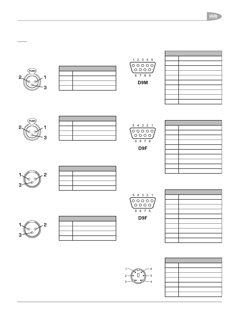
NOTE: Numbers refer to the rear panel diagram on page 10. All
connector views are looking at the rear of the CDR-882.
Connector: XLRF
PIN
USE
1
Screen
2
Signal ‘hot’ (phase)
3
Signal ‘cold’ (anti-phase)
Connector: XLRF
PIN
FUNCTION
1
Screen
2
Data ‘hot’ (phase)
3
Data ‘cold’ (anti-phase)
Connector: XLRM
PIN
FUNCTION
1
Screen
2
Signal ‘hot’ (phase)
3
Signal ‘cold’ (anti-phase)
Connector: XLRM
PIN
FUNCTION
1
Screen
2
Data ‘hot’ (phase)
3
Data ‘cold’ (anti-phase)
Connector: DM
PIN
FUNCTION
1
n/u
2
Data receive
3
Data transmit
4
+5v
5
0v
6
n/u
7
RTS
8
CTS
9
n/u
Connector: DF
PIN
FUNCTION
1
n/u
2
Data transmit
3
Data receive
4
+5v
5
0v
6
n/u
7
CTS
8
RTS
9
n/u
Connector: DF
PIN
FUNCTION
1
Input 1
2
Input 2
3
Input 3
4
Input 4
5
Input 5
6
0v
7
Output 1
8
Output 2
9
Output 3
Connector: PS/ socket
PIN
FUNCTION
1
Clock
2
Gnd
3
Data
4
n/c
5
Vcc
6
n/c
Multi-Machine RS232 Link Input
(male) (11)
Parallel Remote Input
(female) (13)
PS/2 Keyboard (15)
Multi-Machine RS232 Link Output
(female) (4)
Analogue Inputs (Balanced) (1)
AES/EBU Input (3)
Analogue Outputs (Balanced) (6)
AES/EBU Output (8)
Appendix 1 - Connector Pinouts