Wire installation – GE 400 Series 30 Inch Freestanding Electric Range Installation Instructions User Manual
Page 2
2
ATTACH REQUIRED FILLER
TRIM
For ALL front control installations,
the
included filler trim must be installed. Remove
the two screws on rear trim indicated with
nearby arrows. Reuse these two screws to
attach the filler trim to the back of the range.
3
ELECTRICAL CONNECTIONS
WARNING
This appliance must be
properly grounded. Failure to do so can
result in electric shock.
WARNING
All new constructions,
mobile homes, recreational vehicles and
installations where local codes do not
allow grounding through neutral, require a
4-conductor UL-listed range cord.
WARNING
To prevent fire or shock,
do not use an extension cord with this
appliance.
WARNING
To prevent shock, remove
house fuse or open circuit breaker before
beginning installation.
We recommend you have the electrical wiring
and hookup of your range connected by a
qualified electrician. After installation, have
the electrician show you how to disconnect
power from the range.
You must use a single-phase, 120/208 VAC
or 120/240 VAC, 60 hertz electrical system.
If you connect to aluminum wiring, properly
installed connectors approved for use with
aluminum wiring must be used.
Effective January 1, 1996, the National
Electrical Code requires that new
construction (not existing) utilize a
4-conductor connection to an electric range.
When installing an electric range in new
construction, mobile home, recreational
vehicle, or an area where local codes prohibit
grounding through the neutral conductor,
refer to the section on four-conductor branch
circuit connections.
Check with your local utilities for electrical
codes which apply in your area. Failure to
wire your oven according to governing codes
could result in a hazardous condition. If there
are no local codes, your oven must be wired
and fused to meet the National Electrical
Code, NFPA No. 70 – latest edition, available
from the National Fire Protection Association.
This appliance must be supplied with the
proper voltage and frequency, and connected
to an individual, properly grounded, 40 amp
(minimum) branch circuit protected by a
circuit breaker or time-delay fuse.
Use only a 3-conductor or a 4-conductor
UL-listed range cord. These cords may be
provided with ring terminals on wire and
a strain relief device. A range cord rated
at 40 amps with 125/250 minimum volt
range is required. A 50 amp range cord is
not recommended but if used, it should be
marked for use with nominal 1 3⁄8” diameter
connection openings. Care should be taken
to center the cable and strain relief within
the knockout hole to keep the edge from
damaging the cable.
The rating plate is located on the frame
surrounding the drawer.
3
ELECTRICAL CONNECTIONS
(cont.)
Rating plate
4
POWER CORD AND
CONDUIT INSTALLATION
(cont.)
B. For power cord and 1” conduit only,
remove the knockout ring (1 3⁄8”) located
on bracket directly below the terminal
block. To remove the knockout, use a pair
of pliers to bend the knockout ring away
from the bracket and twist until ring is
removed.
C. For power cord installations only (see the
next step if using conduit), assemble the
strain relief in the hole. Insert the power
cord through the strain relief and tighten.
Allow enough slack to easily attach the
cord terminals to the terminal block. If tabs
are present at the end of the winged strain
relief, they can be removed for better fit.
NOTE:
Do not install the power cord
without a strain relief. The strain relief
bracket MUST be installed before
reinstalling the rear range wiring cover.
D. For 3/4” conduit installations only, purchase
a squeeze connector matching the
diameter of your conduit and assemble
it in the hole. Insert the conduit through
the squeeze connector and tighten. Allow
enough slack to easily attach the wires to
the terminal block.
NOTE:
Do not install
the conduit without a squeeze connector.
The squeeze connector MUST be installed
before reinstalling the rear range wire or
terminal block cover.
PROCEED TO STEP 4 OR 5.
4
POWER CORD AND
CONDUIT INSTALLATION
A. Remove wire cover (on the back of
range) by removing screws using a 1/4”
nut driver. You can access the terminal
block by removing the wire cover. Do not
discard these screws.
Wire cover
Wire
Cover
Screws
Back of range
Knockout
ring in
bracket
Knockout
ring removed
Terminal block
(appearance
may vary)
Power cord
Strain relief
Terminal
block
Bracket
Squeeze
connector
Terminal block
Conduit
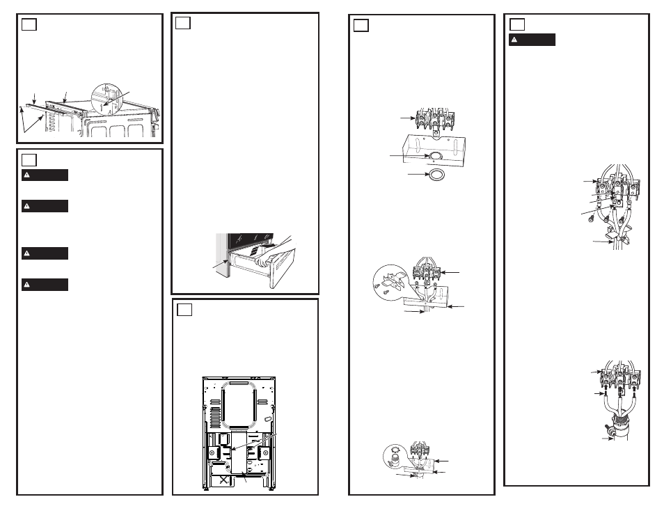
Bracket
5
3-WIRE INSTALLATION
WARNING
The neutral or ground wire
of the power cord must be connected to the
neutral terminal located in the center of the
terminal block and the ground strap must
connect the neutral terminal to the ground
plate. The power leads must be connected to
the lower left and the lower right terminals of
the terminal block.
DO NOT
remove the ground strap
connection.
FOR POWER CORD INSTALLATION
A. Remove the 3 lower terminal screws from
the terminal block.
B. Insert the
3 terminal
screws
through
each
power cord
terminal
ring and
into the
lower
terminals of
the terminal
block. Be
certain that the center wire (white/neutral)
is connected to the center lower position
of the terminal block.
C. Tighten screws securely into the terminal
block.
FOR CONDUIT INSTALLATION
A. Loosen the 3 lower terminal screws on
the terminal block. Strip wire to expose tip
about 5/8” long.
B. Insert the center (white/neutral) wire tip
through the bottom center terminal block
opening. On
certain models, the
wire will need to be
inserted through
the ground strap
opening and then
into the bottom
center block
opening. Insert the
two side bare wire
tips into the lower
left and the lower
right terminal block openings.
C. Tighten the screws until the wire is firmly
secured (35 to 50 inch-lbs.). Do not over-
tighten the screws.
Terminal block
(appearance
may vary)
Power cord
Power Cord
Neutral terminal
Ground strap
Ground
plate
Wire
tips
Terminal
block
Conduit
Conduit
Screws
Filler Trim
Rear Trim
Arrows on
both sides
Back of Range
- 600 Series 30 Inch Slide-In Electric Smart Range Installation Instructions 600 Series 30 Inch Freestanding Electric Smart Range Installation Instructions 500 Series 30 Inch Freestanding Electric Range Installation Instructions 400 Series 30 Inch Freestanding Electric Smart Range Installation Instructions 500 Series 30 Inch Slide-In Electric Range Installation Instructions