GE 400 Series 30 Inch Freestanding Electric Range Installation Instructions User Manual
Installation instructions electric ranges, Before you begin, For your safety
Questions? Call GE Appliances at 1.800.GE.CARES (1.800.432.2737) or visit
GEAppliances.com.
BEFORE YOU BEGIN
Read these instructions completely and carefully.
• IMPORTANT –
Save these instructions for
local inspector’s use.
• IMPORTANT –
Observe all governing codes
and ordinances.
• Note to Installer –
Be sure to leave these
instructions with the Consumer.
• Note to Consumer –
Keep these instructions
for future reference.
• Note to Servicer –
The electrical diagram is
in an envelope attached to the left side panel,
when the drawer is removed.
•
Proper installation is the responsibility of
installer.
•
Product failure due to improper installation is
not covered under the Warranty.
•
IMPORTANT —
Remove all packing material
and literature from oven before connecting gas
and electrical supply to range.
• Skill level
– Installation of this appliance
requires basic mechanical skills and advanced
electrical skills.
FOR YOUR SAFETY:
If you did not receive an anti-tip bracket with your
purchase, call 1.800.626.8774 to receive one at
no cost. For installation instructions of the bracket,
visit:
GEAppliances.com.
Remove any
currently used
anti-tip bracket
and install with
the provided
anti-tip bracket and
screws.
WARNING
Before beginning the
installation, switch
power off at service
panel and lock the
service disconnecting
means to prevent power
from being switched on
accidentally. When the
service disconnecting
means cannot be
locked, securely fasten
a prominent warning
device, such as a tag,
to the service panel.
Anti-Tip
Bracket
and
screws
Included
• A child or adult can tip the range and be killed.
• Install the anti-tip bracket provided with the unit
to the wall or floor.
• Engage the range to the anti-tip bracket by sliding the
range back such that the foot is engaged.
• Re-engage the anti-tip bracket if the range is moved.
• Failure to do so can result in death or serious burns
to children or adults.
Tip-Over Hazard
WARNING
MATERIALS YOU MAY NEED
TOOLS YOU WILL NEED
Squeeze Connector
(For Conduit
Installations Only)
(UL Listed 40 AMP)
4-Wire Cord 4’ long OR
3-Wire Cord 4’ long
Drill
Safety Glasses
Adjustable Wrench
Phillips Screwdriver
Level
Tape Measure
Pliers
1/4” Nut Driver
PROPER DISPOSAL OF YOUR
APPLIANCE
Dispose of or recycle your appliance
in accordance with Federal and Local
Regulations. Contact your local authorities for
the environmentally safe disposal or recycling
of your appliance.
WARNING
Remove existing anti-tip
bracket from install space, if present.
Installation Instructions
Electric Ranges
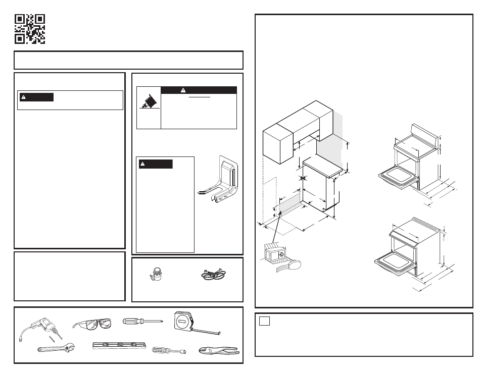
DIMENSIONS AND CLEARANCES
Make sure the wall covering, countertop,
flooring and cabinets around the range can
withstand the heat (up to 200°F) generated by
the range.
Allow 30” minimum clearance between surface
units and bottom of unprotected wood or metal
cabinet, or allow a 24” minimum when bottom
of wood or metal cabinet is protected by no
less than 1/4” thick flame retardant millboard
covered with not less than No 28 MSG sheet
metal, (.015”), .015” thick stainless steel, .024”
aluminum or .020” copper.
Orient electrical receptacle so the length is
parallel to floor.
This appliance has been approved for 0”
spacing to adjacent surfaces above the
cooktop. However, a 6” minimum spacing to
surfaces less than 15” above the cooktop and
adjacent cabinet is recommended to reduce
exposure to steam, grease splatter and heat.
To reduce the risk of burns or fire when
reaching over hot surface elements, cabinet
storage space above the cooktop should be
avoided. If cabinet storage space is to be
provided above the cooktop, the risk can be
reduced by installing a range hood that projects
at least 5” beyond the front of the cabinets.
Cabinets installed above the cooktop must be
no deeper than 16”.
Recommended
Wall-mounted
0”
Minimum
to cabinets
below
cooktop
30”
(see note)
0”
minimum
to cabinets
above
counter
30”
0”
Right side
0”
Left side
Minimum
to side wall
36”
30”
3 1/4”
6 1/2”
24”
23 3/4”
3 1/8”
Side Wall
Electrical
supply
NOTE:
Use a 4’ power cord to
prevent interference with the
storage drawer. Power cords
41⁄2’ to 6’ long may have to
be dressed to allow for proper
drawer closing.
1
REMOVE PACKAGING MATERIALS:
Failure to remove packaging materials could
result in damage to the appliance. Remove
all packing parts from oven, racks, heating
elements and drawer. Also, remove protective
film and labels on the outer door, cooktop and
control panel.
Consider recycling options for your appliance
packaging material.
REAR CONTROL
47
1/2"
Door Open
30"
NOTE:
Rear wall to
front of door glass.
25 1/2"
w/o handle
10 3/4"
35
5/8"
to
36
1/2"
27
7/8"
with
handle
FRONT CONTROL
30"
5/8"
28 5/8"
with handle
35
5/8”
to
36
1/2”
NOTE:
Rear wall to
front of door glass.
26
1/4"
w/o handle
48
1/4"
Door Open
NOTE:
Minimum to
bare cabinet above: see
Installation Instructions
for alternate installation
configurations.
- 600 Series 30 Inch Slide-In Electric Smart Range Installation Instructions 600 Series 30 Inch Freestanding Electric Smart Range Installation Instructions 500 Series 30 Inch Freestanding Electric Range Installation Instructions 400 Series 30 Inch Freestanding Electric Smart Range Installation Instructions 500 Series 30 Inch Slide-In Electric Range Installation Instructions