Introduction, Unpacking and visual checks, Installation – Lab.gruppen E2:2 200W E-Series Installation Amplifier with 2 Flexible Output Channels User Manual
Page 7: Cooling, Operating voltage, Grounding, Audio inputs, Loudspeaker outputs, Front panel rear panel
12
E Series
Quick Start Guide
13
Introduction
The information contained in this Quick Start Guide is sufficient for proper installation of E Series amplifiers, and for configuration of settings in typical applications.
Please refer to the full Operation Manual for detailed information on maintenance, cooling requirements, warranty, and configuration for complex installations.
Unpacking and visual checks
Every Lab Gruppen amplifier is carefully tested and inspected before leaving the factory and should arrive in perfect condition. If any damage is discovered,
please notify the shipping carrier immediately. Save the packing materials for the carrier’s inspection and for any future shipping.
Installation
Free air flow from front to rear is required for cooling. No doors or covers should be mounted either in front of or behind the amplifiers.
Amplifiers may be stacked directly on top of each other with no spacing, though some spacing may enable more convenient installation of rear cabling.
See the specifiication page for size and weights.
WARNING: Please refer to the information on the label located on the product top cover for electrical and safety information before installing or operating the device.
Cooling
E Series devices use a forced–air cooling system with airflow from front to rear, allowing high continuous power levels without thermal problems. Ensure that there
is sufficient space in front of and behind the amplifiers to allow for fee air flow. Please refer to the full Operation Manual for thermal dissipation value when installing
large numbers of amplifiers in air conditioned spaces.
NOTE: Fit solid blanks (not ventilation blanks) to unused rack spaces to ensure effective air ciculation. Leaving gaps in between items of equipment degrades the
effectiveness of forced-air cooling.
Operating voltage
All E Series amplifiers have a universal power supply that operates on mains from 100 – 240 V at 50 or 60 Hz. The IEC receptacle on the rear panel accepts the
supplied IEC cord which terminates in a connector appropriate for the country of sale. When AC power is connected, the amplifier goes into standby
(amber indication on power LEDs). It will go on if the power button is pressed (or if signal is supplied to either input or if the GPI is closed).
The power LED shows green for “on” indication.
Grounding
For safety reasons, never disconnect the earth (ground) pin on the AC power cord. Use balanced input connections to avoid hum and interference.
Signal ground is floating via a resistor to chassis, and therefore grounding is automatic.
Audio inputs
Audio inputs are electronically balanced and use three-pole Phoenix-type connectors. Follow the +, - and Ground labels when making connections.
Loudspeaker outputs
Loudspeaker outputs use detachable block-type connectors.
Maximum connector current rating is 41 Arms (exceeding capacity
of the amplifier). Cables up to 4 mm2 (12 AWG) can be accommodated.
Observe polarity to avoid low frequency cancellation loss.
Note:
A channel
’
s amplifier module is based on an inherently bridged topology. DO NOT CONNECT ANY TERMINAL TO GROUND.
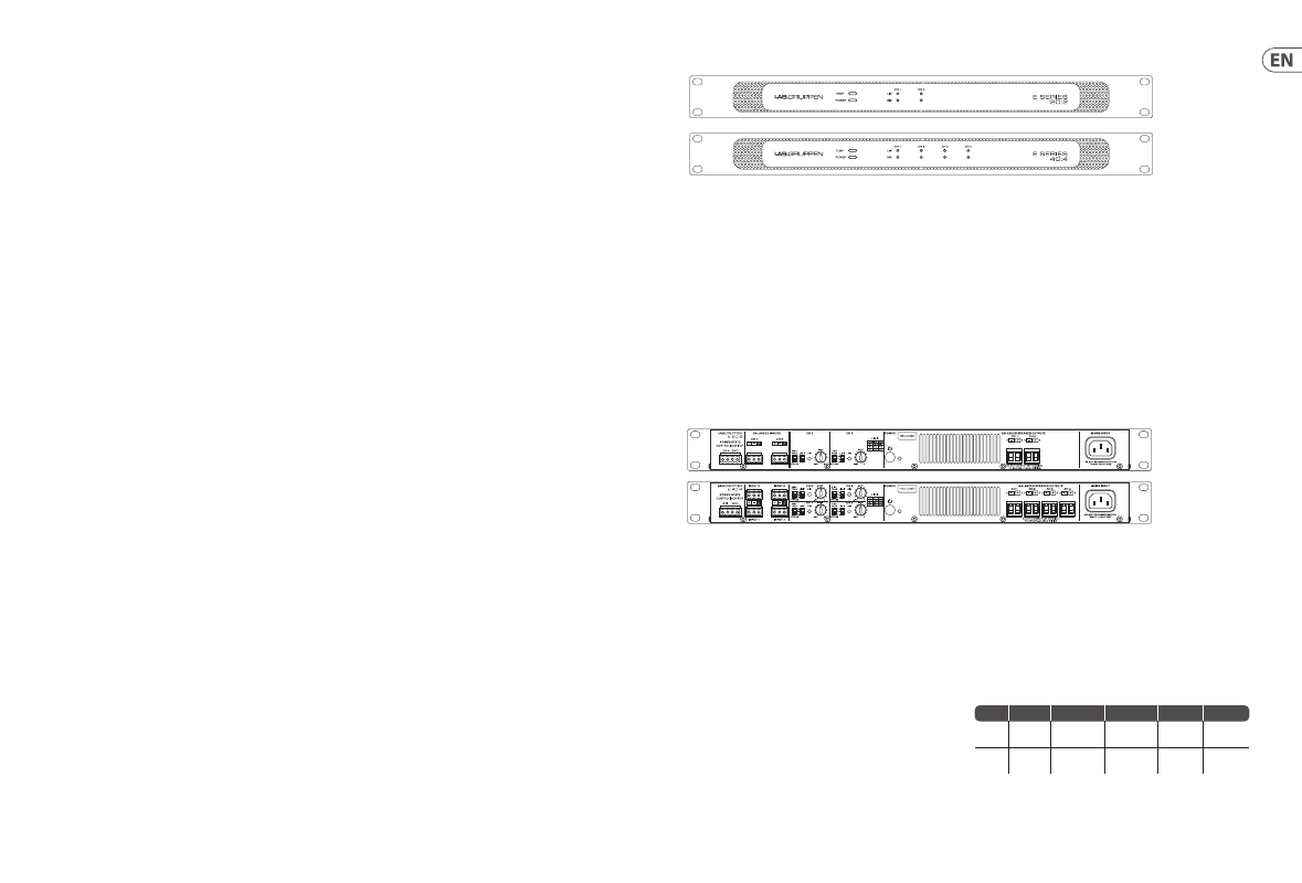
Front panel
Rear panel
The front panel presents the following amplifier status indicators:
POWER
– Bi-color LED indicates standby (amber) and on (green).
TEMP
(temperature) – Flashing yellow indicates excessive temperature in the
power supply unit (PSU) or output stage(s). When temperature exceeds the
danger threshold, the LED shows steady yellow and the amplifier mutes.
SIG
(input signal present) - Green indication when input signal exceeds signal
present threshold.
LIM
(limit) – Illuminates when the amplifier limits the signal. Limiting is
engaged when the channel:
• Reaches the selected voltage limit threshold (as determined by model
and position on the limit switch)
• Rail voltage sags below the selected threshold
• Maximum current output reached
• Mains voltage cannot maintain rail voltage
Important note on Auto Power On/Off
– All E Series amplifiers include an
Auto Power Down/On (APD) scheme. As shipped (factory default), the amplifier
will go to low power standby mode when no signal is present for 20 minutes.
It will return to power on mode when signal exceeds the signal present
threshold. For information on calibrating the signal present threshold,
please refer to the Operation Manual.
Power button and indication
– When pressed momentarily, toggles power
state between standby and on. Indicator shows amber for when it goes into
standby, amber if it is forced into standby by pressing the power knob, and green
for on.
Attenuators
– Range is 0 dB to -infinity; vertical is -10 dB. Amplifier sensitivity is
4 dBu with attenuator at 0 dB and 14 dBu at -10 dB.
SIG
– Illuminates green when input signal above Signal Present Threshold (SPT).
For adjustment of SPT value, please refer to the full Operation Manual.
High-pass / Full-range
– Selects flat or high-pass filter at 50 Hz.
Limit switch
– See specification page for switch settings.
The E Series can also be used asymmetrically; i.e. one channel delivers more than
the other(s). Please download the operational manual for examples at
www.labgruppen.com/support/download
GPIO
– GPIO allows use of external relays for power on and off. See the Operation
Manual for information on GPIO facilities.
70V / Lo-Z (E 5:4 and E 10:4)
– The 70V position should be selected for constant
voltage systems. 100V loudspeakers can be driven, but the power will be half of
the selected tap. The 70V position is also used for full rated power into 16 ohm
loads. The Lo-Z position should be selected for full power into 2 or 4 ohm loads,
or for limiting maximum output into 16 ohms. For 8 ohm, see the following table.
4 Ω
8 Ω (Lo-Z/Hi-Z) 16 Ω (Lo-Z/Hi-Z)
70 V
100 V
E 10:4
1 dBu:
250 W
4 dBu: 250 W
“
4dBu: 125 W /
3 dBu: 250 W*
”
4 dBu:
250 W*
4 dBu:
250 W*
E 5:4
1 dBu:
125 W
4 dBu: 125 W
“
4dBu: 63 W /
0 dBu: 125 W*
”
4 dBu:
125 W*
4 dBu:
125 W*
*If the
“
70V
”
mode is used