LowFlow Mark 708SH Series Short Pattern 1/4 User Manual
Page 3
-3-
Clean all parts with an approved non-residue-form-
6.
ing solvent. Remove encrusted material with a very
fine Crocus or aluminum oxide cloth. However, do
not use these abrasives on the seating surface or
the trim surface (the portion of the plug that enters
the seat bore.) The machining tolerances on these
surfaces are so closely controlled that you might
change the valves flow characteristic.
Inspect all parts and replace and worn or damaged
7.
parts. It is always advisable to replace seals and
gaskets. DO NOT attempt to resurface seating sur-
faces of the plug or seat. Seats and plugs are only
sold in factory-matched sets.
Valve Reassembly
Soft seated valves: insert soft seat into the seat
1.
cavity, install the seat cap and tighten.
Lubricate the seat threads with a lubricant such as
2.
NO-LOK and thread the seat into the body. Torque
to values shown.
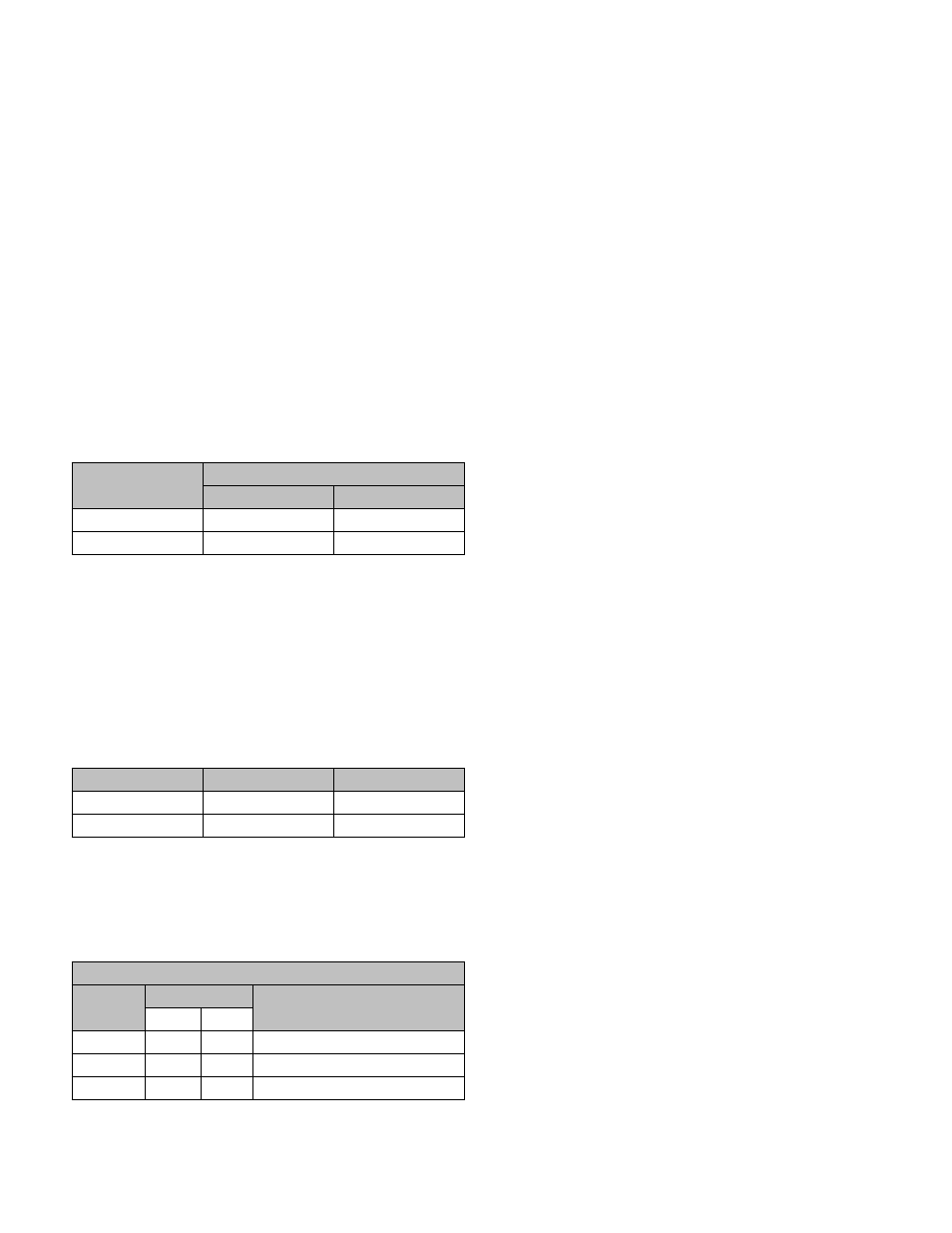
Valve Size
Seat Torque
ft. - lbs.
in. - lbs.
3/4”
26
310
1/2”
20
240
Guided trim: coat the guide portion of the plug
3.
with MOLYKOTE G-Rapid Spray lubricant or an
equivalent light lubricant suitable for your service.
Assemble plug to stem.
Insert the stem into the bonnet. Set the gasket
4.
around the boss on the bonnet. Carefully assemble
the bonnet to the body and allow the plug to center
into the seat. Push down on the stem to be sure
that the plug has fully engaged the seat. Hand-
tighten the body bolts.
Valve Size
Gasket Material
Quantity Required
All
Teflon
1
1/2” & 3/4”
Grafoil
2
Remove and replace the packing as described in
5.
“Packing Replacement”.
While holding the plug firmly in position in the
6.
seat, secure the body to the bonnet with the bolts.
Torque bolts evenly to the values shown.
Torque Values (in. - lbs.)
Material
Bolt Diameter
Limitation
5/16”
3/8”
Gr. BD*
125
200
650 deg. (also SAE GR. 8)
Gr. B7
125
200
1000 deg. F
Gr. B6
125
200
900 deg. F (410 SST)
* Standard Bolting
Reassemble the two stem nuts and indicator all the
7.
way onto the stem threads.
If the actuator is reverse acting (ATO), apply ap-
8.
proximately 6 psig air pressure to the actuator. If
MOTOR VALVE, position to full open.
Insert hex bolts through the yoke and into the bon-
9.
net flange. Next, place the packing adaptor (7)
into the packing box, and then the packing gland
(9) over the top of the packing adaptor. Secure
the packing gland with the gland nuts (11). Thread
the stem into the actuator stem. Hold the actuator
stem with a wrench to prevent it from turning. In-
stall the nuts onto yoke hex bolts and tighten. (You
can press down on the actuator to compress the
springs and bring the yoke into contact with the
bonnet flange.) The actuator spring preload must
be adjusted; refer to “Actuator Spring Preload Ad-
justment”. For Motor Valve see “Motor Valve Seat
Spring Pre-Load”.
Actuator Spring Preload Adjustment
The two stem nuts should be loosened and thread-
1.
ed down on the stem and then locked together.
Lock the valve stem into the stem connector, then
thread the stem connector in the actuator stem.
A regulated air supply must be provided to the
2.
actuator. Connect the air to the lower case for re-
verse acting or to the upper case for direct action
actuators.
Standard actuators have ranges of either 3-15 psig
3.
or 6-30 psig. The range is stamped on the valve
nameplate. These instructions will assume that the
range is 3-15. If yours differs, substitute the appro-
priate pressure where these instructions refer to 3
or 15 psig.
4a. Direct Acting Actuator (ATC): Slowly increase the
air pressure up to 15 psig while observing the stem
for movement. Downward travel should stop ex-
actly at 15 psig. If the downward travel stops before
15 psig is reached, thread the stem connector into
the actuator stem by wrenching on the locked stem
nuts and keeping the actuator stem from turning to
avoid twisting the diaphragm and/or toppling the
springs. If the downward travel continues after 15
psig is reached, thread the stem connector out of
the actuator stem.
4b. Reverse Acting Actuator (ATO): The valve plug
is closed against upward fluid thrust by actuator
spring force. Total compression placed on the ac-
tuator spring must be sufficient to provide preload
plug force required to close the valve. If preload
adjustment is made with no pressure in valve body,
then, when the control valve is placed in opera-
tion, additional compression must be placed on the
spring to provide valve closure force. With proper
adjustment, valve will close tightly and will not be-
gin to open until the preload pressure is exceeded.
Slowly increase the air pressure up to 3 psig while
observing the stem for movement. Adjust spring
preload until valve just starts to open when 3 psig
air pressure is supplied to the actuator diaphragm.